


Copyright 2003 OutBack Power Systems, Inc. FX & VFX Series Inverter/Charger System Installation & Programming Manual
19009 62
nd
Ave NE, Arlington WA 98223 USA 900-0027-1
Tel 360 435 6030 Fax 360 435 6019
Rev 7.2 08/26/05 Page 47
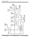
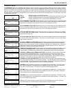
MATE SCREENS
WARNING MENU
The WARNINGS section of the STATUS menu allows the user to check the cause of a warning condition for the FX. When a warning
condition has occurred, the red “ERROR” LED indicator in the FX’s wiring compartment will flash. The cause of the warning will not be
displayed on the MATE like an ERROR will. Instead, you must access this WARNINGS menu and scroll down the list to find out which
warning is present. This is indicated by the presence of a “YES” next to the appropriate cause listed. Once the cause for the warning is
no longer present, the display will change back to “NO” as shown below and the red LED will stop flashing. A warning will not shut the
FX down like an error will.
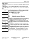
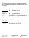
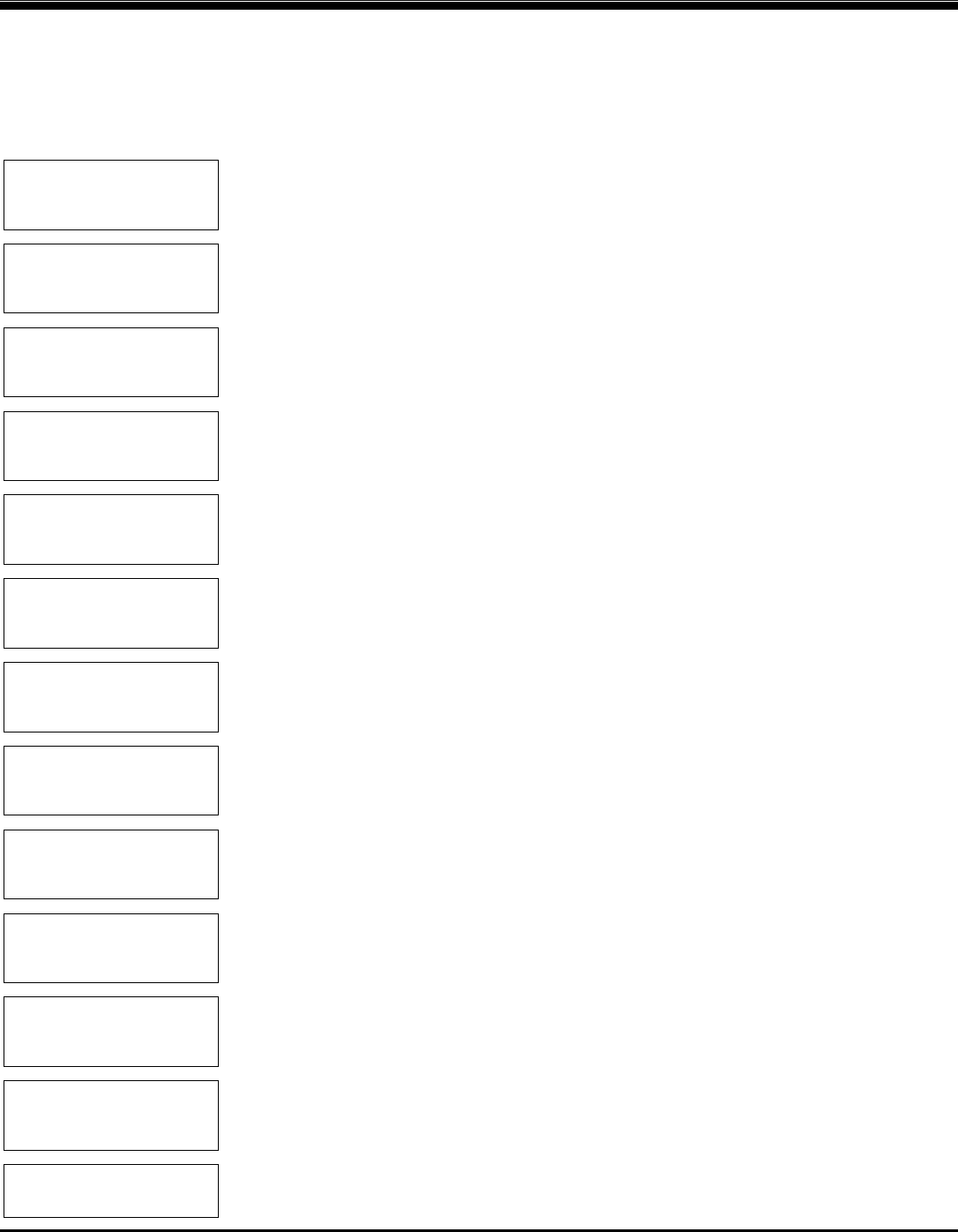
STATUS/FX/PAGE2-----
choose category:
PG1 ERROR WARN PG3
↓
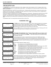
STATUS/FX/WARN---P00
acin freq No
too high
DOWN STATUS PORT
↓
STATUS/FX/WARN---P00
acin freq No
too low
DOWN UP TOP PORT
↓
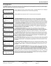
STATUS/FX/WARN---P00
acin voltage No
too high
DOWN UP TOP PORT
↓
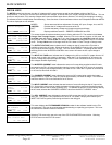
STATUS/FX/WARN---P00
acin voltage No
too low
DOWN UP TOP PORT
↓
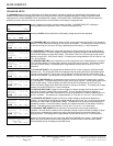
STATUS/FX/WARN---P00
ac input No
current exceeds max
DOWN UP TOP PORT
↓
STATUS/FX/WARN---P00
temperature No
sensor fault
DOWN UP TOP PORT
↓
STATUS/FX/WARN---P00
internal comm No
error detected
DOWN UP TOP PORT
↓
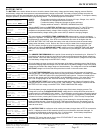
STATUS/FX/WARN---P00
internal fan No
failure detected
DOWN UP TOP PORT
↓
STATUS/FX/WARN---P00
airtemp 206
DOWN UP PORT
↓
STATUS/FX/WARN---P00
fettemp 200
DOWN UP PORT
↓
STATUS/FX/WARN---P00
captemp 203
DOWN UP PORT
↓
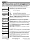
STATUS/FX/WARN------
end of warnings menu
UP TOP STATUS
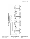
PG1 Returns to page 1 of the STATUS section
ERROR Displays the different causes for errors and qualifies each cause with a Yes or No
<WARN> Displays the different causes for warnings and qualifies each with a Yes or No
PG3 Displays additional sections – reason for last DISCONNECT and SELL
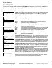
AC IN FREQUENCY TOO HIGH indicates that the AC input connected to the FX is above the upper
limit of its frequency window and will not connect to the AC source if the frequency stays this high. If
the frequency of the AC source is above 66 Hz, the FX will display this warning.
AC IN FREQUENCY TOO LOW indicates that the AC input connected to the FX is below the lower
limit of its frequency window and will not connect to the AC source if the frequency stays this low. If
the frequency of the AC source is below 54 Hz, the FX will display this warning.
AC IN VOLTAGE TOO HIGH indicates that the AC source’s voltage is over the upper limit (default
is 140 VAC) of the FX’s voltage window. The FX will not connect to the AC source until the voltage
drops below the upper limit.
AC IN VOLTAGE TOO LOW indicates that the AC source’s voltage is below the lower limit (default
is 108 VAC) of the FX’s voltage window. The FX will not connect to the AC source until the voltage
rises above the lower limit.
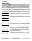
AC INPUT CURRENT EXCEEDS MAX indicates that the AC loads are drawing more current than
the AC INPUT LIMIT of the FX is programmed for. Exceeding this current limit for an extended
period of time could cause the FX to fail, a generator to disconnect or a breaker to trip. Reduce the
loads on the FX’s AC output to prevent damage and, for Mobile versions of the FX, make sure a
30A breaker (maximum) is used on the AC input line.
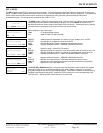
TEMPERATURE SENSOR FAULT indicates that one of the temperature sensors internally located
in the FX is not working correctly. The FX needs to be checked by a qualified repair technician.
The AIRTEMP, FETTEMP and CAPTEMP screens shown below can help with troubleshooting.
INTERNAL COMMUNICATION ERROR DETECTED indicates that a communication problem has
occurred between the MATE and the FX. This warning may occur if the communication lines
between the FX and the MATE have been severed or disconnected. If this is the case, connect a
working cable and perform a “Re-Poll” of the system using the MATE. See the MATE manual for
instructions. If this does not solve the problem, call your dealer for assistance.
INTERNAL FAN FAILURE DETECTED warns that the fan mounted above the transformer inside
the FX has stopped working or is not functioning properly. This will eventually cause an INVERTER
OVERTEMP error if the cause of the fan failure is not fixed. Restart the FX and listen for the fan to
verify a fan failure. The fan should run for about 15 seconds on start-up.
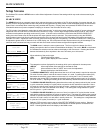
AIRTEMP shows a numerical value that the FX understands as a temperature. The value comes
from a sensor inside the FX that measures the temperature of the air (or transformer, depending
upon the FX’s serial number). This warning is given for troubleshooting purposes.
FETTEMP shows a numerical value that the FX understands as a temperature. The value comes
from a sensor inside the FX that measures the temperature of the FETs (Field Effect Transistors).
This warning is given for troubleshooting purposes.
CAPTEMP shows a numerical value that the FX understands as a temperature. The value comes
from a sensor inside the FX that measures the temperature of the ripple capacitors. This warning is
given for troubleshooting purposes.
Selecting TOP returns the user to the top of the STATUS/FX/WARN menu section. Selecting
STATUS returns to the STATUS screen to allow selection of another product.