


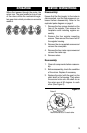


1. OMEGA recommends that when set-
ting up pipework for meter installations,
a bypass line be included in the de-
sign. This provides the facility for a
meter to be removed for maintenance
without interrupting production. (See
Figure 1)
2
NOTE: Incorrect installation can cause pre-
mature wear of meter components
7. Do not overtighten meter connections.
8. It is important that after initial installa-
tion you fill the line slowly, high speed
air purge could cause damage to the
rotors.
9. Test the system for leaks.
10. Check the strainer for swarf or foreign
material. After the first 200 litres, check
periodically – particularly if the flowrate
decreases.
2. Use thread sealant on all pipe threads.
3. For pump applications, ensure pipe
work has the appropriate working pres-
sure rating to match the pressure out-
put of the pump.
4. Install a wire mesh strainer (Y or bas-
ket type 60 mesh) as close as possible
to the inlet side of the meter.
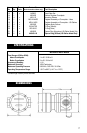
5. Ensure that the meter is installed so
that the flow of the liquid is in the di-
rection of the arrows embossed on the
meter body.
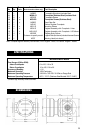
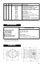
6. The meter can be installed in any ori-
entation as long as the meter shafts are
in a horizontal plane. (See Figure 2) The
register assembly may be oriented to
suit the individual installation.
INSTALLATION
Figure 1
Flow Outlet
Bypass Line
Strainer
Flow Inlet
Figure 2
R I G H T
➧
➧
W R O N G
R I G H T
➧