


1-2
This manual contains detailed operating instructions for all
aspects of the FD6000 instruments. The following condensed
instructions are provided to assist the operator in getting
the instrument started up and running as quickly as
possible. This pertains to basic operation only. If specific
instrument features are to be used or if the installer is
unfamiliar with this type of instrument, refer to the
appropriate section in the manual for complete details.
1. TRANSDUCER LOCATION
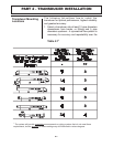
A. In general, select a mounting location on the piping
system with a minimum of 10 pipe diameters (10 X the
pipe inside diameter) of straight pipe upstream and 5
straight diameters downsteam. See Table 2.1 for
additional configurations.
B. On horizontal pipe, select a position that is between 2
and 4 o’clock on the pipe, with 12 o’clock representing
the top. Installations on vertical pipe should be made
in an area where the flow moves from bottom to top—
ensuring a full pipe of liquid.
2. PIPE PREP ARATIO N AND TR ANSDUCER
MOUNTING
A. The piping surface, where the transducers are to be
mounted, needs to be clean and dry. Remove loose
scale, rust and paint to ensure satisfactory acoustical
bonds.
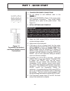
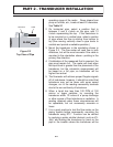
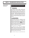
B. Loosely wrap the appropriate length of strap around
the pipe at the location determined in Step 1. Refer to
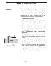
Figure 1.1 for proper orientation of the transducer. For
greatest accuracy, point the cable of the transducer in
the primary flow direction.
C. Apply a liberal amount of couplant onto the transducer
face. Place the transducer onto the pipe ensuring
square and true placement. If an RTV type of
couplant (requiring curing time) was utilized, allow
sufficient time for curing before applying power to the
instrument or moving the cable.
PART 1 - QUICK START
General
FLOW
Figure 1.1
Top View of Pipe
Transducer Cable