


FUEL 2100 Installation and Operation ManualNAVMAN
8
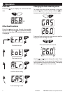
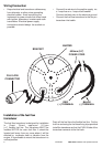
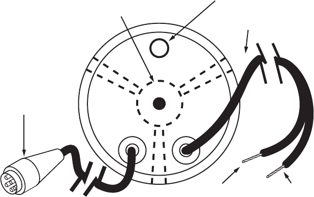
Wiring Connection
• Keep electrical and transducer cables away
from alternator or other noise generating
electrical cables. Avoid connecting the
instrument to power circuits that share loads
with ignition, alternators, inverters and radio
transmitters. Electrical power supply
connections should always be as short as
possible.
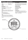
600mm (24”)
POWER CORD
BRACKET
BUZZER
RED
(+) TERMINAL
BLACK
(-) TERMINAL
FUJI 5-PIN
CONNECTOR
• Connect the red wire to the positive supply via
a 1 amp fuse or a 1 amp circuit breaker.
Connect the black wire to the electrical ground.
• Connect the fuel flow transducer to the five pin
transducer inlet cable.
Installation of the fuel flow
transducer
The fuel flow transducer is designed for installation
in Coast Guard approved 9.5 mm
(
3
/8”) flexible fuel line. The transducer MUST be
installed AFTER the main fuel filter. It should be
located well away from any area where it will be
effected by excessive heat or vibration from the
engine. It is preferable to mount the transducer in a
vertical position.
Drain all the fuel from the flexible fuel line. Cut the
fuel line and using the fuel hose fixing clips provided
install the transducer so that the FUEL IN side of the
transducer connects to the fuel tank.