


Murphy - Keystart 9620 series installation instructions 00-02-0657 revision A 22
nd
September 2008 p3/4
Terminal functions (cont.)
Pin Function
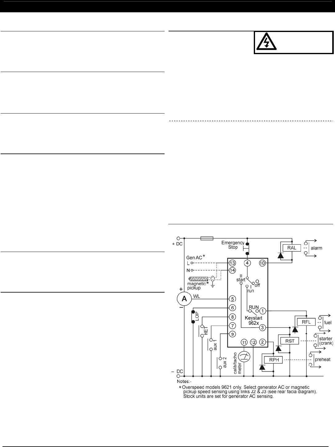
3 Start (crank) output
Pin 3 gives a positive DC, 16 Amp rated output when the key
is switched to position II (start/crank). To prolong keyswitch
contact life, connect a slave relay (with suppressed coil)
between pin 3 and the engine starter solenoid coil - see
‘typical connection’ diagram below.
4
12
Power Supply, Positive DC
Power Supply, Negative DC
The Keystart operates with any smooth DC / battery voltage in
the range 7 – 30V. Supply brown-out protection is fitted as
standard. Connect a 5 Amp anti-surge fuse in the positive DC
line (pin 4).
5 Charge fail
The charge fail LED lights, but there is no shutdown or alarm,
when pin 5 is connected to battery negative. When using a
charge alternator, connect pin 5 to the alternator warning lamp
(WL) terminal. (Note: pin 5 supplies the alternator excitation
current).
6
7
8
9
Low Oil Pressure (LOP) fault input
Auxiliary 1 fault input
High Engine Temperature (HET) fault input
Auxiliary 2 fault input
Use remote switch/relay contacts that connect these inputs
to battery negative during fault conditions. The Keystart
shuts down the engine, lights the appropriate fault LED,
and activates the alarm output. Note: activation of pin 9
(Aux 2 input) causes engine shutdown and illumination of
the overspeed LED.
For all the above inputs, shutdown is inhibited during engine
cranking and until the end of the fault ‘override’ time (adjustable
2 – 20 secs using potentiometer VR1, clockwise to increase).
To reset a shutdown fault condition, turn the key to O (Off) or
remove the DC power supply.
10 Alarm output
Pin 10 is a semiconductor-based (open collector NPN transistor)
output that gives a negative DC output immediately after a fault
shutdown. Output rating is 250mA max.: the output typically
drives an audible/visible alarm circuit, using a slave relay with
suppressed coil - see ‘typical connection’ opposite.
11
Tachometer (speed calibration) output
This output is designed to work with a 0 - 1 mA DC ammeter,
either a) during set-up to aid speed calibration, or b) in normal
operation to indicate engine speed or generator Hz.
For calibration, connect meter positive to pin 11 and meter
negative to battery negative, e.g. at terminal 12. See ‘speed
sensing and calibration’ below for setup procedure.
For indication of engine RPM or generator Hz, the 0 – 1mA
meter requires a custom scale: when correctly calibrated
using VR2, Keystart gives 0 mA at 0 RPM/Hz. and 0.75mA
(3/4 scale) at normal running RPM/Hz.
Pin Function
13
14
With links J2 & J3 ON:
Generator AC Live
Generator AC Neutral
DANGER !
HIGH VOLTS
When configuration links J2 and J3 are fitted (the default factory
setting), terminals 13 and 14 are configured for overspeed
sensing using a high voltage, generator AC 50/60Hz. signal.
The input accepts generator AC voltages between 70 and
270 VAC rms. A 1 Amp anti-surge fuse should be connected
in series with AC live (pin 13). See ‘speed sensing’ below for
correct calibration of this input using potentiometers VR2 and
VR3.
To configure these terminals to magnetic pickup engine
speed sensing, see section below.
13
14
With links J2 & J3 OFF:
Magnetic pickup signal input
Magnetic pickup return
When configuration links J2 and J3 are removed, terminals 13
and 14 are configured for speed sensing by a magnetic pickup
and flywheel/gearwheel combination.
Connect the magnetic pickup to the input using two-core and
screen cable. To minimise electrical interference on the speed
signal, connect the cable screen to earth at one end only.
Magnetic pickup signal requirements are 10 – 60 VAC peak,
with frequency between 2000 and 6500 Hz. when the engine is
running at nominal speed. See ‘speed sensing’ below for correct
calibration of this input using potentiometers VR2 and VR3.
To configure these terminals for generator AC frequency
sensing, see section above.
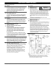
Typical connection
ELECTRICAL CONNECTION (cont.)