


Murphy - Keystart 9620 series installation instructions 00-02-0657 revision A 22
nd
September 2008 p2/4
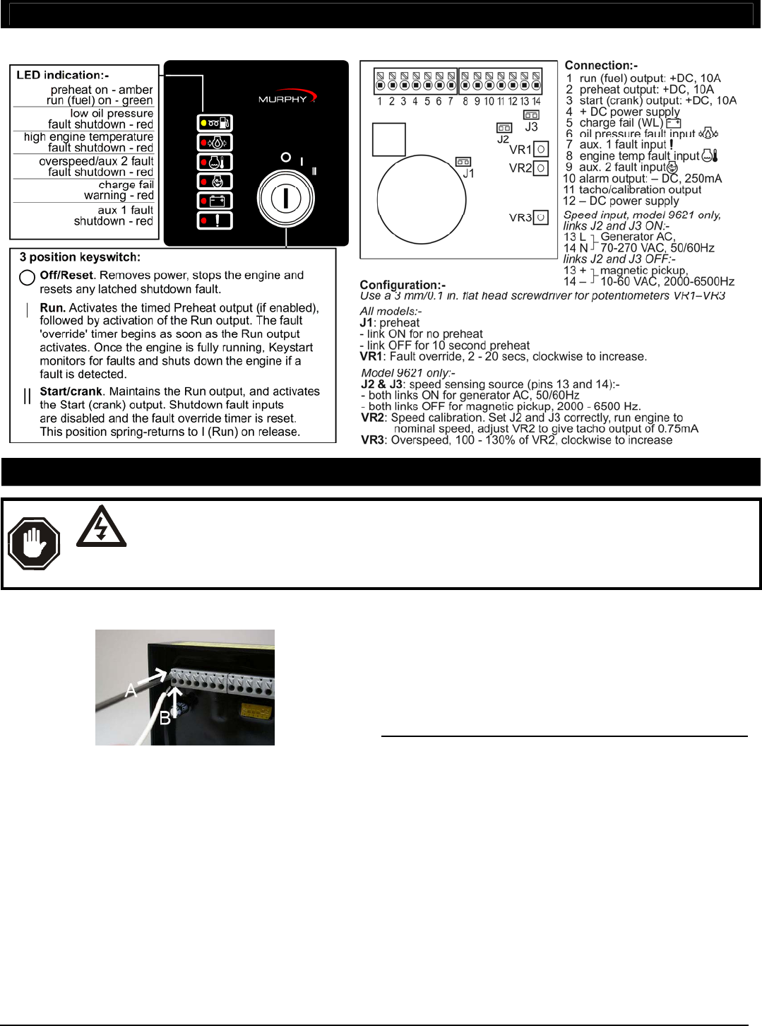
Electrical connection to 0.5 to 1.5 mm² / 16 – 20 AWG panel wiring is
by spring-clamp terminals at the rear.
•
pre-strip 8 to 10 mm / 0.3 to 0.4 in. of insulation from each wire.
• Above each terminal is a square push-button with a diagonal slot.
Insert a flat-head screwdriver into the slot (A), then push down to
(towards the front of the Keystart) to open the terminal clamp.
• insert the wire into the terminal (B), checking that the insulation is
clear of the clamp. Release the screwdriver/spring clamp pressure
and check that the wire is secure.
General connection recommendations
Murphy make several recommendations for the electrical connection
of engine and generator controllers.
• minimise controller output load current (i.e. wear/tear and potential
damage) by using slave relays between the controller outputs and
high power end-devices such as fuel and starter solenoids.
• Suppress (at source) electrical interference from panel relay and
engine solenoid coils, using flywheel diode or proprietary snubber
networks as appropriate.
• use separate routing for AC and DC wiring harnesses.
• use separate wiring for a) connection of battery charger to battery,
and b) connection of battery to panel DC supply. Separate wiring will
reduce high frequency battery charger output noise on the panel DC
power supply.
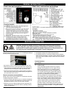
Terminal functions
Pin Function
1
2
Run (fuel) output
Preheat output
These relay outputs provide control for a the engine’s
preheater and (energised to run) fuel / ignition circuits.
When configuration link J3 is on (the default setting),
the Preheat output (terminal 2) does not operate. If link
J3 is removed, terminal 2 gives a positive DC output for
10 seconds, and the preheat LED lights, beginning from
when the key is switched to the I (RUN) position.
After any preheat time has expired, the Run output (pin 1)
gives a positive DC output (operating engine fuel) and the
green ‘run’ LED lights. The Run output and LED remain
active until the operator switches the key to O (STOP) or
until the Keystart initiates an automatic fault shutdown.
Both Run and Preheat outputs are rated 10 Amp max.
@ 24VDC. Murphy recommend the connection of slave
relays with suppressed coils between these outputs and fuel
solenoid coil and engine preheaters - see ‘typical connection’
diagram below.
GENERAL INFORMATION (cont.)
Front view and operation
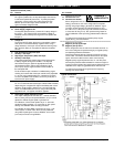
Rear view, connections and settings
ELECTRICAL CONNECTION
DANGER !
HIGH VOLTS
WARNING: DANGER OF INJURY OR DEATH. Keystart 9621 controllers allow connection
of high voltage AC circuits. Before connection, disconnection or handling of these units,
ensure that all AC and DC power supplies are isolated. Connection to or disconnection from
live wiring may also cause damage to the Keystart’s internal components.