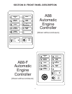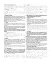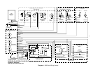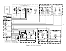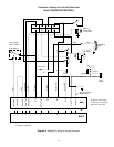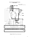
Refer to Diagrams 1 and 3: Basic Wiring Hookup for
correct connections to your engine.
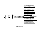
Diagram 2 shows wire colors that correspond to the A88
plug and hookup wire, in the event of two colors the first
color is the primary color and the other is a tracer color.
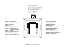
Diagram 4 identifies the A88-F wiring terminals.
Step No. 1, Pickup:
Determine the type of pickup to be used and connect
it to the controller as illustrated in the basic wiring
hookup.
Step No. 2, Starter Solenoid:
Determine the type of starter solenoid used on your
engine. In most cases it will be of the source type, that
is, one side of the pull in coil is connected to ground and
and the other has to be connected through the ignition
to positive. Do not connect the controller output directly
to the starter, always use a starter slave solenoid.
Step No. 3, Ignition:
The type of ignition must be determined and wired
accordingly. Most later models will be of the CDI type.
Step No. 4, Start/Stop
Select the type of Start/Stop control needed and wire
accordingly. If a close to run and open to stop is used
be sure and connect the brown/white and the
grey/white together. On the A-88-F connect terminals
16 and 17. It is recommended that the alarm before
start be used for safety.
Step No. 5, Choke:
If a choke or pressure release feature is needed con-
nect the choke solenoid to battery positive then to
terminal 3 of the A-88-F or to the violet wire of the A-88.
Step No. 6, Shutdown:
Connect the shutdown circuits. The spare should be
marked or labeled on the blank space.
Step No. 7, Time Delay:
This system has a 60 second built-in time delay for
customer use. If the appropriate inputs are grounded, it
times out after the crank disconnect light comes on.
Step No. 8, Clutch or Warmup Operation:
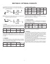
If a warm up feature is desired see Section IV:
Optional Hookups paragraph 5
WARM UP.
Step No. 9, Crank disconnect adjustment:
To adjust the crank disconnect, disconnect the ignition
wire or leave the fuel cut off. That will let the engine
crank but not start.
Turn the crank disconnect control fully clockwise (15
turns). This control does not have a stop and it does
not hurt it to turn it more than 15 turns.
Place the the crank and rest time switch in the 10 or
15 second position. Switch the controller in the test
position. With the engine cranking, rotate the control
counter-clockwise until the starter drops out. Notice
that the engine will crank longer the first time.
When the starter kicks out, rotate the control clock-
wise for approximately 1(one) turn. The crank
disconnect is now set.
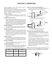
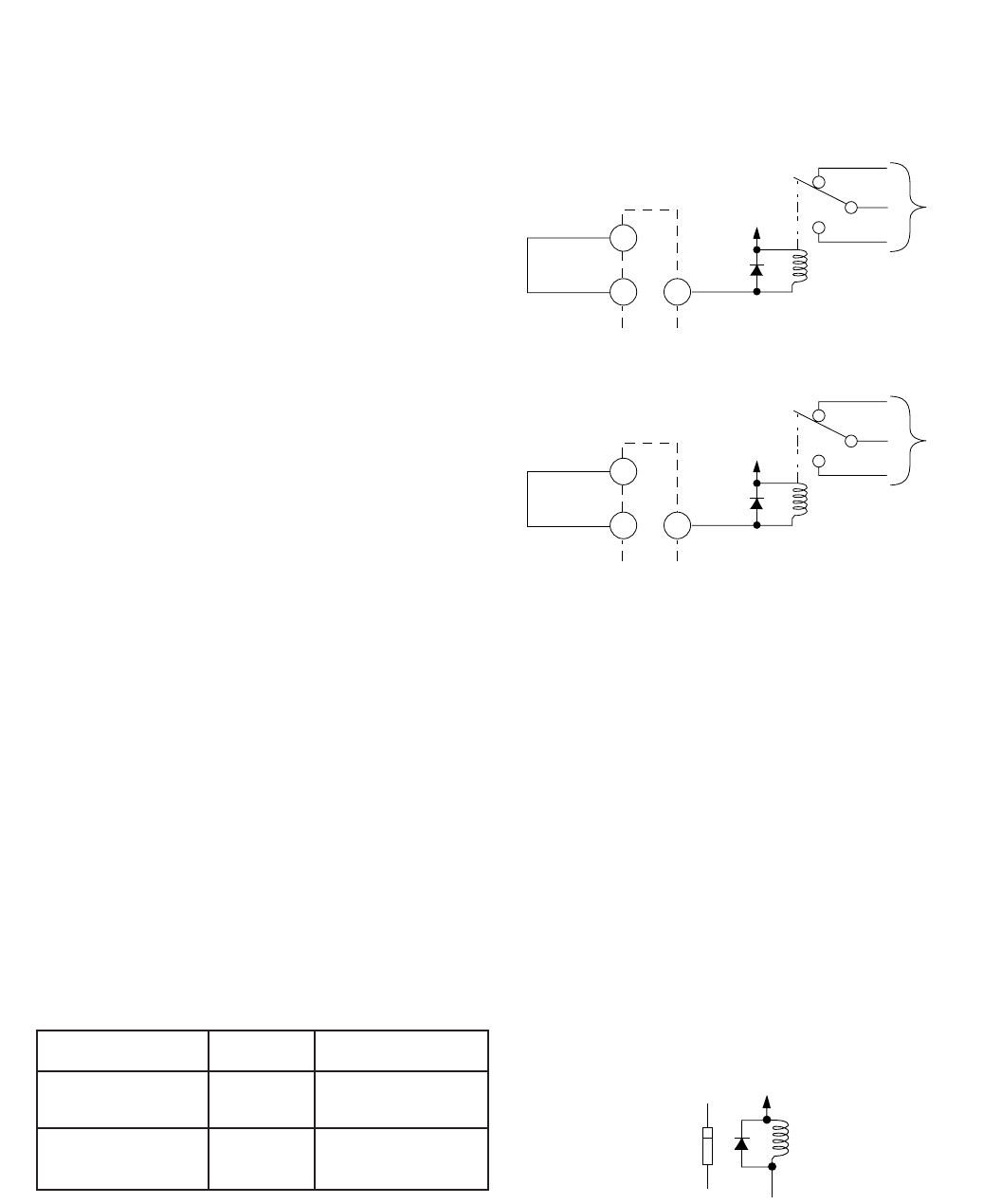
NOTE: When installing relays or solenoids that are
controlled by this controller always install a diode directly
across the coil windings to help eliminate the back EMF.
SECTION V: OPERATION
Batt.+
To
Clutch
Control
Orange
Violet/White
Yellow
Slave
Relay
Diode
Batt.+
18
9 19
To
Clutch
Control
Slave
Relay
Diode
A88
A88-F
Clutch activates approximately 90 seconds after
engine has started—pulls in after engine stops.
Clutch activates approximately 90 seconds after
engine has started—pulls in after engine stops.
Input Delay Output
60
seconds
60
seconds
Orange wire
Sinks to ground
Terminal 19
Sinks to ground
A88 ground
violet/white wire
A88-F ground
Terminal 9
+
Diode
Solenoid
or
Coil
5


