


In this section the terms Sink and Source are used.
Sink: This terms refers to an output that switches to
ground to do work.
Source: This term will be used to refer to an output that is
switched to positive to do work.
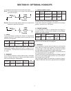
1. CHOKE
To use this feature, connect the choke or compression
release solenoid to the battery positive and then to the
terminal or wire shown:
At the beginning of each crank cycle, the choke or
compression release solenoid will pull in, remain in for 3
or 4 seconds. The maximum current this circuit can carry
is 1 amp.
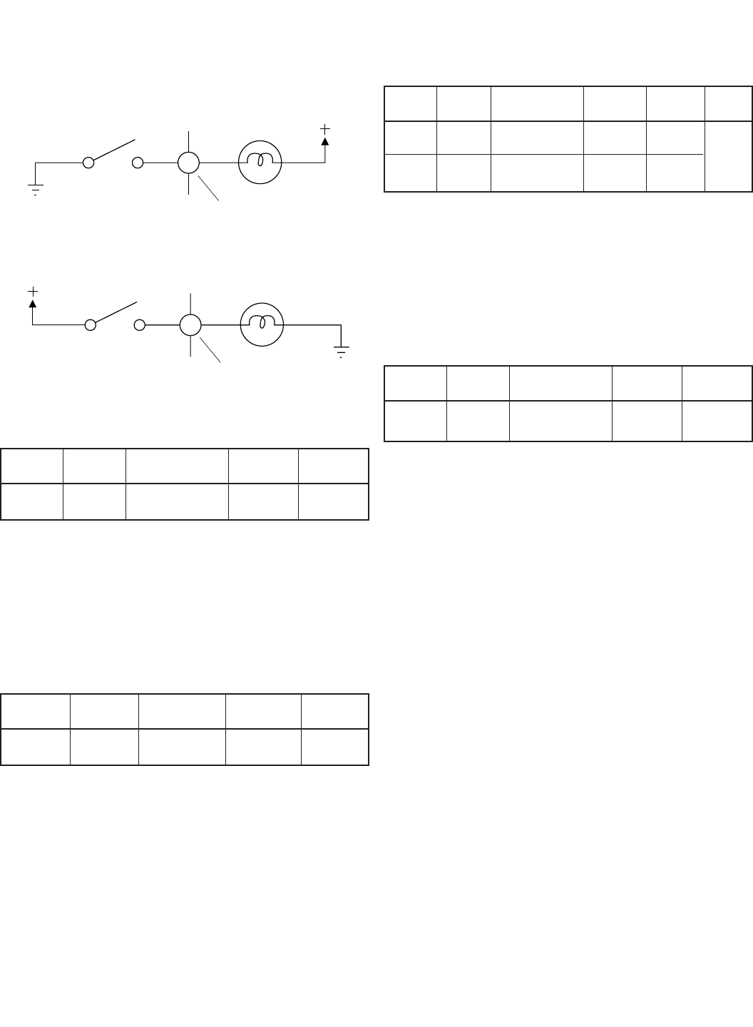
2. SUMMARY
For a remote shutdown or alarm feature after a shutdown
occurs, connect the alarm or lamp to the battery positive
then to the terminal or wires shown:
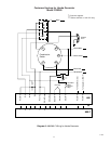
3. CRANK CONNECTIONS
If the crank solenoid is already connected to ground,
connect to the unit as indicated in "A" above.
If the crank solenoid is already connected to the battery
positive, connect it as in "B" above.
4. ENGINE RUNNING
If it is desirable to know or indicate when the engine is
actually running, connect the indicator to the battery
positive and then as below:
After the engine has been running for approximately 30
seconds, the indicator will be energized.
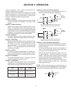
5. WARM UP
If it is desirable to have a warm up period or a 90 second
delay after the engine has started, connect the engine
running output to the time delay input and then connect
the time delay to the gas feed or clutch mechanism.
Terminal 18 to terminal 9 on the A88-F, the yellow wire to
the violet/white wire on the A88 unit.
Connect the clutch or gas feed solenoid to battery positive
then to the time delay output terminal 19 on the A88-F;
the orange wire on the A88.
After the engine starts and has been running for approx-
imately 90 seconds, the clutch or gas feed will be energized.
SECTION IV: OPTIONAL HOOKUPS
Switch
Lamp
Terminal
Switch
Lamp
Terminal
Output
Choke
A88-F
Terminal
No. 3
A88 Wire color
Violet
Output
Operation
Sink
Max.
Current
1 A
Output
Engine
Running
A88-F
Terminal
No. 18
A88 Wire color
Yellow
Output
Operation
After 30
sec. delay
Sink
Max.
Current
1 A
A Crank
B Crank
A88-F
Terminal
No. 1
No. 2
A88 wire color
White/Brown
White/Red
Solenoid
to Ground
Solen. to
batt. pos.
Output
Operation
Connected
Source
Sink
Max.
Current
1 A
Output
Summary
A88-F
Terminal
No. 20
A88
Wire color
Brown
Output
Operation
Sink
1
/2 A
Max.
Current
4