


PAGE 12 — MTX80/90 RAMMER — OPERATION AND PARTS MANUAL — REV. #9 (1/14/11)
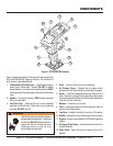
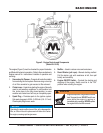
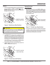
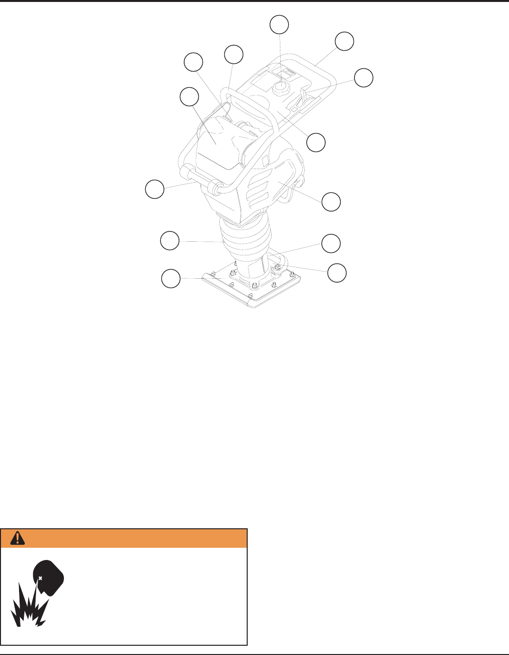
Figure 1 shows the location of the controls and components
for the MTX80/MTX90 Tamping Rammer. The functions of
each control is described below:
1. Combination (Throttle) Lever – Used to adjust engine
speed (rpm). Move lever forward
(SLOW)
to reduce
engine speed, move lever back toward operator
(FAST
)
to increase speed. Always operate the rammer at full speed
(rpm).
2. Handle – To operate rammer,
GRIP
handle assembly
firmly on both sides.
3. Fuel Tank Cap – Remove this cap to add unleaded
gasoline to the fuel tank. Make sure cap is tightened
securely. DO NOT over fill.
Figure 1. MTX80/MTX90 Rammer
4. Hook – Used to lift rammer for transporting.
5. Air Cleaner Cover – Protects the air cleaner which
prevents dirt and other debris from entering the engine.
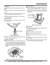
6. Roller – Used for loading the rammer in back end of a
truck. Rammer is brought to tail gate roller side toward
the truck bed and driver lifts roller with handle at base and
rolls the unit into truck bed.
7. Bellows – Reservoir for oil bath.
8. Foot – Laminated wood with tempered steel plate for
superior shock absorption.
9. Fuel Tank – Holds the fuel for the unit (up to 3.2 quarts)
10. Muffler – reduces the noise of the engine when running.
11. Engine – this unit uses a Robin EH122D46530 gasoline
engine.
12. Oil Gauge (Sight Glass) – Indicates the level of oil in the
oil bath reservoir.
13. Drain Valve – Open this valve to remove oil from the
bellows.
2
1
9
3
4
5
6
7
10
11
12
13
8
COMPONENTS
WARNING
Add fuel to the tank only when the engine is
stopped and has cooled down. In the event
of a fuel spill, DO NOT attempt to start the
engine until the fuel residue has been
completely wiped up and the area
surrounding the engine is dry.