


DCA25SSIU3 60 HZ GENERATOR • OPERATION AND PARTS MANUAL — REV. #0 (12/20/10) — PAGE 33
GENERATOR START-UP PROCEDURE
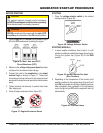
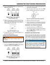
3. Turn the ignition key to the start position (Figure 41).
Once the engine starts, release the ignition key and allow
it to return to the RUN position (Figure 39).
If the engine fails to start after 10 seconds, wait
approximately 30 seconds and repeat steps 3-4.
Figure 41. Ignition Switch (Start Position)
4. Let the engine run for 1-2 minutes. Listen for any
abnormal noises. If any abnormalities exist, shut down
the engine and correct the problem.
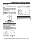
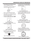
5. The generator’s frequency meter (Figure 42) should
be displaying the 60 cycle output frequency in HERTZ.
Figure 42. Frequency Meter
6. The generator’s AC-voltmeter (Figure 43) will display
the generator’s output in VOLTS..
Figure 43. Voltmeter Meter
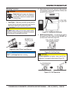
7. If the voltage is not within the specifi ed tolerance use
the voltage adjustment control knob (Figure 44) to
increase or decrease the desired voltage.
Figure 44. Voltage Adjust Control Knob
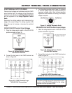
8. The ammeter (Figure 45) will indicate zero amps with
no load applied. When a load is applied, the ammeter
will indicate the amount of current that the load is
drawing from the generator.
Figure 45. Ammeter (No Load)
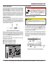
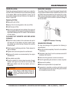
9. The engine oil pressure gauge (Figure 46) will
indicate the oil pressure of the engine. Under normal
operating conditions the oil pressure is approximately
28 to 71 psi. (193~490 kPa).
Figure 46. Oil Pressure Gauge
10. The coolant temperature gauge (Figure 47) will
indicate the coolant temperature. Under normal
operating conditions the coolant temperature should
be between 165°~203°F (74°~95°C) (Green Zone).
Figure 47. Coolant Temperature Gauge
11. The tachometer gauge (Figure 48) will indicate the
speed of the engine when the generator is operating.
Under normal operating conditions this speed is
approximately 1800 RPM’s.
Figure 48. Engine Tachometer Gauge