


E-4
Mr. Heater | Big Buddy Operating Instructions and Owner’s Manual
LIGHTING / OPERATING INSTRUCTIONS
FOR USE WITH HOSE(S) CONNECTED TO
A REMOTE CYLINDER, MAXIMUM SIZE 20
LBS:
• WARNING: ANY HOSE CONNECTION TO A QUICK DIS-
CONNECT FITTING ON HEATER MUST BE REGULATED
TO 11” W.C. PRESSURE
• This Heater may be used in a Recreational Enclosure or
Temporary Construction Work Enclosure with a Remote
Refillable Propane Cylinder ONLY when the Cylinder
is Located Outdoors and the Heater is Used with Mr.
Heater Hose No. F273701, F273702 or F272702 and fuel
lter F273699. Fuel lter must be replaced annually.
• Mr. Heater Hose No. F271802 which includes a quick
disconnect fitting and a 3/8” female flare fitting con-
nected to a regulated (11” W.C.) propane source.
• Mr. Heater Hose No. F271803 which includes a quick
disconnect fitting and a 11” W.C. regulator.
• DANGER: NEVER bring a refillable propane cylinder
indoors. A re or explosion can occur causing property
damage, serious injury or death!
• Inspect the hose before each use of the heater. If there
is excessive abrasion or wear, or the hose is cut, replace
prior to using the heater with one of the Mr. Heater
Hose No’s. shown above.
• The propane cylinder must include a listed overfilling
protection device as well as a collar to protect the cylin-
der valve.
• Heater must be in an upright position during operation.
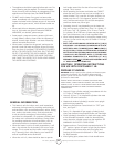
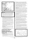
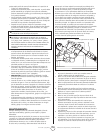
• Make sure ve-position Control Knob is in “OFF” posi-
tion; see Figure 1, at left.
• Screw hose connector into regulator on heater or con-
nect to quick disconnect and screw connector on other
end of hose into LP-gas supply cylinder valve. Tighten all
hose connections.
• Mr. Heater strongly recommends using disposable fuel
lter F273699 to trap any oil substances when connect-
ed to a remote cylinder that can make heater inoper-
able.
• Open valve at LP-gas supply cylinder.
• Check all hose connections for leaks with soapy water at
the threaded connection under the domed plastic cover
to fully extended position. To operate heater slightly
depress knob and gently turn to lock in desired position.
• Turn control knob to “LO” or “MD” position to light
heater. Leave on “LO” or “MD” position until the left
burner tile has turned bright orange.
• After left burner tile has turned bright orange, adjust
heat output by turning Control Knob to desired position
(“LO”, “MD” or “HI”). Note: Both tiles turn orange only
on HI setting.
Warning:
DO NOT OPERATE HEATER UNLESS CONTROL KNOB IS LOCKED
IN A POSITION MARKED “HI”, “MD”, “LO” or “PILOT”. NEVER
SET CONTROL KNOB BETWEEN LOCKED POSITIONS. POOR
COMBUSTION AND HIGHER LEVELS OF CARBON MONOXIDE
MAY RESULT.
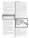
• For added heat circulation turn red fan switch to on. The
fan switch is located just left of control knob side handle
support. See Figure 1.
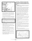
• Installation of 4 D-cell batteries is required for fan
operation. Battery box is located on lower back panel of
heater. Follow instructions on battery cover for correct
battery installation. See gure 2.
• Heater can also be powered by electrical adapter
F276127. Required adapter to be 6 volt DC up to 800 mil-
liamp current with positive tip polarity. See gure 2.
• To shut off heater, slightly push down and turn Control
Knob clockwise to “OFF” position.
• CAUTION: After turning heater off, wire guard will
remain hot. Allow to thoroughly cool before storing.
• Do not operate, store or remove cylinder(s) near am-
mable items or ignition sources.
• LP-GAS CYLINDERS MUST BE DISCONNECTED FROM
HEATER WHEN NOT IN USE!
Figure1
Control Knob
Fan Switch
Figure 2
Electrical Adapter Outlet
Electrical adapter
and batteries not included.