


3
www.moxa.com
info@moxa.com
Serial-to-Ethernet Solutions
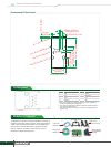
Pin Assignment
Pin Function Pin Function
1 GND 5 Data In
2 VCC 6 Ready/RTS
a
3 Reset 7 DIO
b
4 Data Out 8 CTS
c
a. Pin 6 can be configured as Ready/RTS (Request to Send), Ready/DO, or
RS-485 Tx Enabled (default is Ready/RTS)
b. Pin 7 can be configured as DIO, Modem Control Out, RS-485 Tx Enable, or
Reset to Default (default is DIO)
c. Pin 8 can be configured as CTS (Clear to Send), DI, or Modem Control In
(default is CTS)
The MiiNePort E1 Starter Kit includes the MiiNePort E1 module, an
evaluation board, power adaptor, software, and serial and Ethernet
cables to allow quick and easy evaluation of all embedded device
server functions. The evaluation board is equipped with serial,
Ethernet, digital I/O, and power circuits to help you test your
MiiNePort E1 modules and applications.
MiiNePort E1 Starter Kit
Cross-over
Ethernet Cable
Null Modem Cable
Power Cord
(US or Euro plug)
Document &
Software CD
Power Adaptor
(90 to 240 VAC,
12 VDC)
Evaluation Board
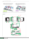
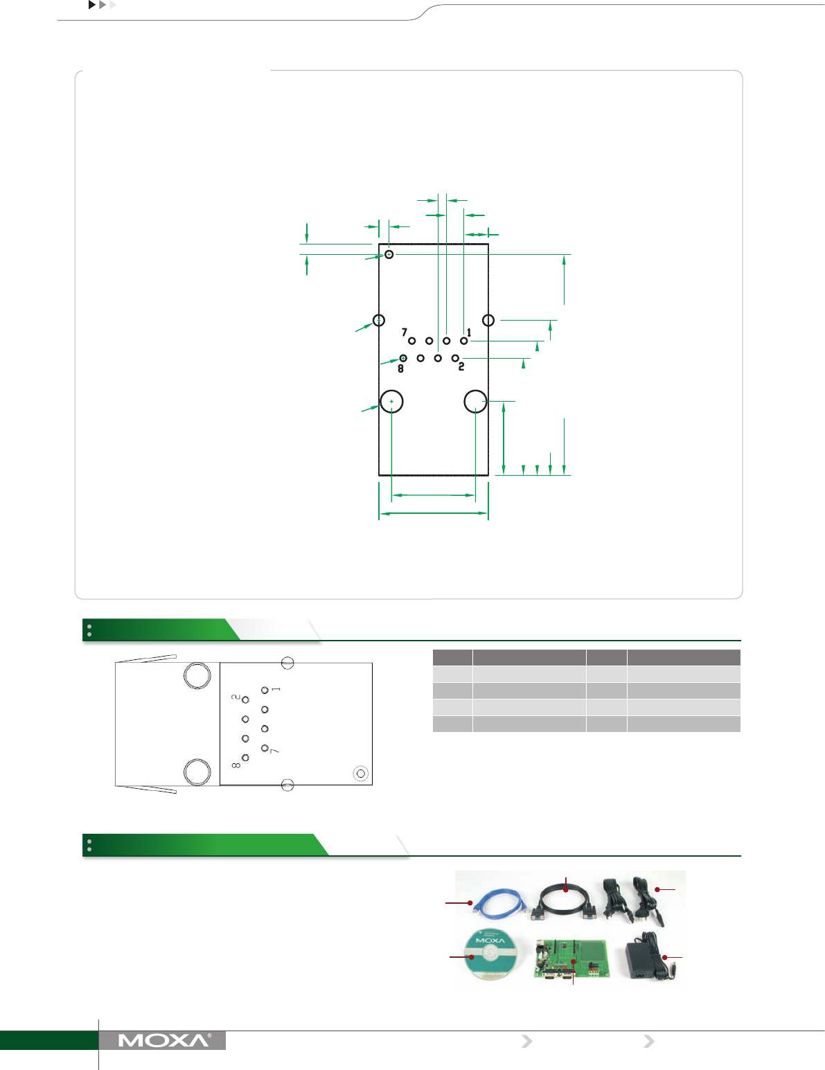
Recommended PC Board Layout
32.4 mm (1.28 in)
3.58 mm (0.14 in)
16.05 mm (0.63 in)
12.3 mm
(0.48 in)
2.54 mm (0.1 in)
1.27 mm (0.05 in)
22.74 mm (0.9 in)
19.73 mm (0.78 in)
17.19 mm (0.68 in)
1.5 mm (0.06 in)
ø1.1 mm (ø0.04 in)
2-ø1.6 mm (ø0.06 in)
8-ø0.9 mm (ø0.04 in)
2-ø3.25 mm (ø0.13 in)
10.84 mm
(0.43 in)
1.5 mm
(0.06 in)