


ENGINE <4D6> -
On-vehicle Service
11C-11
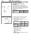
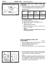
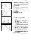
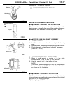
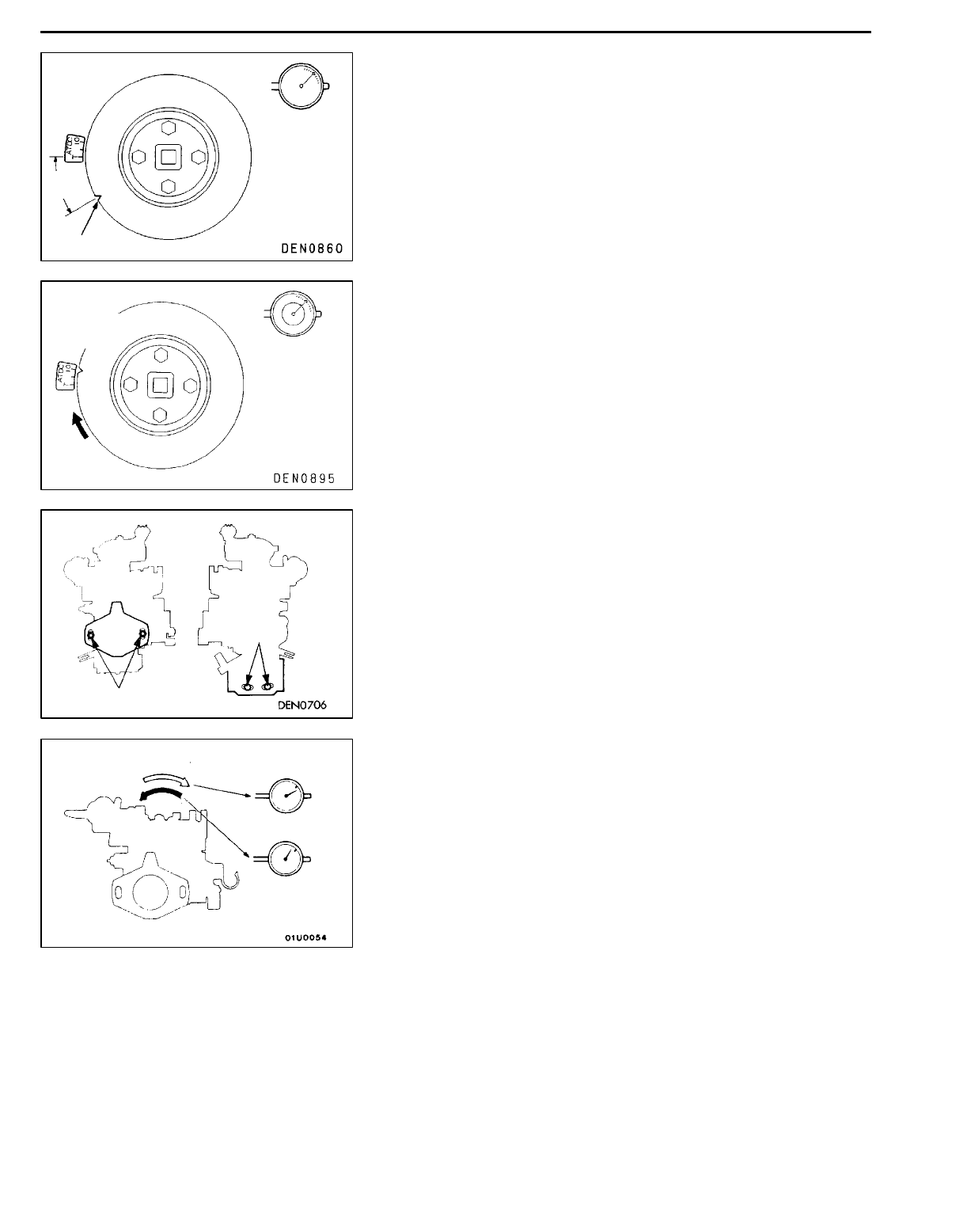
7. Turn the crankshaft clockwise to move the No.1 cylinder
approximately 30_ before compression top dead centre.
8. Set the needle of the dial gauge to 0.
9. Check that the needle doesn’t move even if the crankshaft
is turned slightly (2 - 3_) in both clockwise and
anti-clockwise direction.
NOTE
If the needle moves, the notch is not positioned properly,
so once again move the No.1 cylinder approximately 30_
before compression top dead centre.
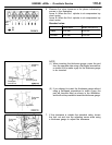
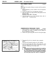
10. Turn the crankshaft clockwise to align th e No.1 cylinder
to 10_ ATDC.
11. Check that the value indicated on the dial gauge is at
the standard value.
Standard value: 1
±
0.03 mm
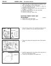
12. If the value is outside the standard value, adjust the
injection timing by the following procedure.
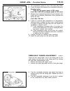
(1) Loosen the injection pipe union nuts (4 places) on
the injection pump. (Do not remove the union nuts.)
Caution
When loosening the nuts, hold the delivery valve
holders with a spanner so that they don’t turn
at the same time.
(2) Loosen the upper mounting nuts and the lower
mounting bolts of the injection pump. (Do not remove
the nut and bolt.)
(3) Tilt the injection pump to the left or right a n d adjust
the needle on the dial gauge so that the display value
is uniform.
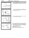
(4) Provisionally tighten the mounting nuts and bolts of
the injection pump.
(5) Repeat steps 7 - 12 to check if the adjustment has
been made correctly.
(6) Tighten the mounting nuts and bolts securely.
(7) Tighten the injection pump union nuts securely.
Caution
When tightening the nuts, hold the delivery valve
holders with a spanner so that they don’t turn
at the same time.
13. Remove the special tool.
14. Install a new gasket to the timing check plug.
15. Tighten the timing check plug securely.
Set to 0
Approx.
30
_
Timing mark
Set to 10
_
ATDC
1
±
0.03 mm
Nuts
Bolts
When the value is
1
±
0.03 mm or more
When the value
is 1
±
0.03 mm
or less