


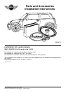
EN/7
Retrofit/installation kit No.: 82 83 0 136 491
Installation instruction No.: 01 29 0 139 395 Status: 06.2001
4. Installing and connecting adapter lead and power cable
0
0
0
0
0
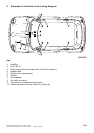
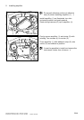
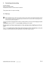
As illustrated, install adapter lead
A
as follows:
Route branch
A1
and
A2
to installation location
of radio.
Route branch
A4
to place of installation of
instrument cluster.
Route branch
A3
and
A5
through rubber
grommet (1) into engine compartment and use
sealing compound to seal off rubber grommet (1)
from engine side.
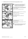
Fit excess length of wiring harness (2) under
instrument panel in passenger footwell and secure
in a suitable position with a cable strap.
0
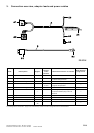
Plug connector
X9345
is to be connected to
branch
A1
on vehicles equipped with a
CD changer.
3
Connect black 17-pin radio plug connector
X2519
(a) to branch
A1
, black 17-pin pin housing
of adapter lead
A
.
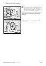
Connect branch
A2
, black 17-pin socket housing,
of adapter lead
A
to the radio.
0
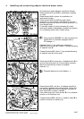
Route branch
A3
, brown wire, of adapter lead
A
to
ground terminal point (a) in the engine compart-
ment and connect by means of adapter
element (1).
Reinstall battery box and battery.
3
0
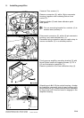
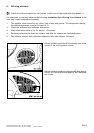
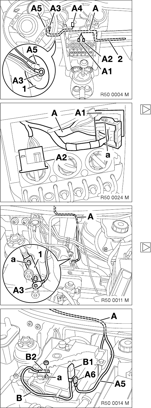
Route branch
A5
, red wire, of adapter lead
A
to
connection location and cut to length. Crimp flat-
pin terminal
A6
onto branch
A5
and connect to
fuse holder
B1
of power cable
B
.
Use cable strap to fix fuse holder
B1
in a suitable
position in the battery box.
Connect branch
B2
, red wire, of power cable
B
to
positive terminal of battery (a).