


EN/6
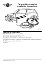
Retrofit/installation kit No.: 82 83 0 136 491
Installation instruction No.: 01 29 0 139 395 Status: 06.2001
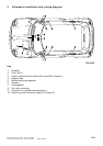
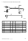
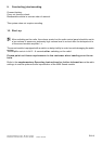
3. Connection overview, adapter leads and power cables
0
0
The X-designations marked with * apply to this overview only and do not refer to the general service documentation.
Item Description Signal
Wire
colour/
cross
section
Connection location in vehicle
Designation/
plug-in slot
A Adapter lead
--- --- --- ---
A1 17-pin pin housing
--- ---
17-pin radio plug connector X2519
on vehicle wiring harness
X2*
A2 17-pin socket housing
--- ---
radio in instrument panel X2519
A3 Cable shoe 6 mm Ground brown/
4 mm
2
ground terminal point, splashboard
in engine compartment
---
A4 25-pin socket housing
--- ---
amplifier X1*
A5 Stranded wire
---
red/4 mm
2
cut to length, crimp on supplied flat-
pin terminal A6 and plug into fuse
holder B1
---
A6 Flat-pin terminal
--- ---
crimp on branch A5
---
B Power cable
--- --- --- ---
B1 Fuse holder with fuse (20 A)
--- ---
secure in battery box
---
B2 Cable shoe 6 mm Terminal
30
red/4 mm
2
battery positive terminal
---