


6
7
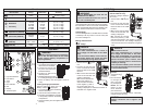
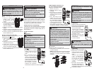
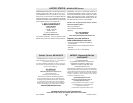
Resistance
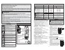
1. Set the Dial to
position.
2. Connect the red test lead
to the V terminal and the
black test lead to the COM
terminal.
Confirm “OL” is indicated
on the display, and then
short-circuit the tips of test
leads to make the indication
zero.
3. Connect the test leads to
the both ends of the resistor
under test.
4. The reading is displayed.
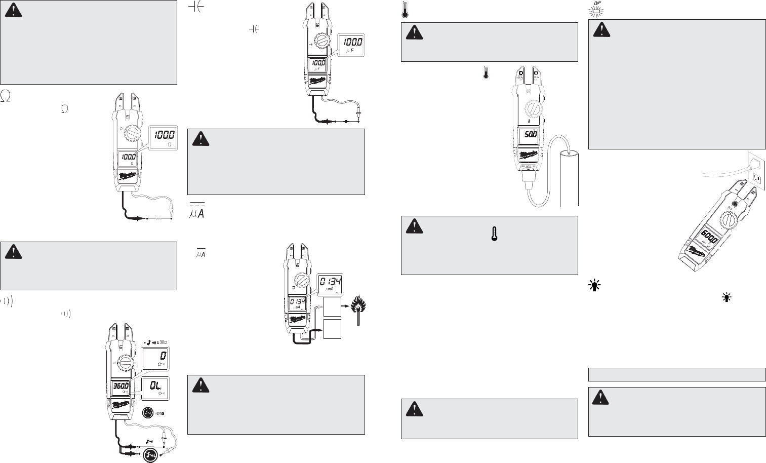
Continuity
1. Set the Dial to
position.
2. Connect the red test lead
to the V terminal and the
black test lead to the COM
terminal.
Confi rm “OL” is indicated
on the display, and then
short-circuit the tips of
test leads to make the
indication zero. A buzzer
will sound.
3. Connect the test leads
to the both ends of the
conductor under test. If
the resistance under test
is 30 or less, the buzzer
will sound.
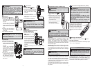
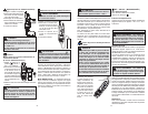
Capacitance
(Cat. No. 2206-20 only)
1. Set the Dial to
position.
2. Connect the red test lead
to the V terminal and the
black test lead to the COM
terminal.
3. Discharge capacitor.
4. Connect the test leads to the
both ends of the capacitor
under test.
5. The reading is displayed.
CAUTION
When current fl ows from the display side to
the underside of the meter, the polarity is
positive; fl ow from underside to display side,
the polarity is negative.
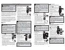
Current
Flame Rectifi cation Circuit Test
(Cat. No. 2206-20 only)
1. Set the Rotary Dial to
position. DC mark
is displayed.
2. Connect the red test
lead to the V terminal
and the black test lead
to the COM terminal.
Contact the red test
lead to the fl ame sen-
sor probe and the black
test lead to the control
module.
3. Turn on the heating unit. The reading is dis-
played.
DANGER
To avoid electrical shock:
Never make measurement on a circuit in
which voltage over AC 1000V or DC 1000V
exists.
Do not use with the Battery Cover removed.
Flame
sensor
probe
Control
Module
DANGER
To reduce the risk of electric shock for
Resistance, Continuity, and Capacitance
measurements, never use the meter on an
energized circuit. Make sure a capacitor is
fully discharged before touching or attempt-
ing to make a measurement.
Do not use with the Battery Cover removed.
CAUTION
After shorting the test leads, the displayed
value may not be zero due to the resistance
of test leads themselves.
WARNING
Never connect the Temperature Probe to an
energized circuit.
CAUTION
When the dial is set to , the room tempera-
ture should be displayed. If anything else is
displayed, something may wrong with the
meter. Stop using the meter immediately.
Temperature (Cat. No. 2206-20 only)
CAUTION
The Data Hold readings are released when the
meter enteres Sleep Mode.
Non-Contact Voltage Detection (NCVD)
Sleep Mode
The meter is automatically powered off in about 20
min after the last Rotary Dial or button operation.
To reset, turn the Rotary Dial to OFF. If the display
is still blank when a new Rotary Dial setting is
selected, replace the batteries.
The meter does use battery power in sleep mode.
Be sure to switch the tool to OFF to conserve bat-
tery power.
ACCESSORIES
For a complete listing of accessories refer to your
MILWAUKEE Electric Tool catalog or go online to
www.milwaukeetool.com. To obtain a catalog, con-
tact your local distributor or a service center listed
on the back cover of this operator’s manual.
WARNING Always remove batteries
before changing or removing accessories. Only
use accessories specifi cally recommended for
this tool. Others may be hazardous.
DANGER
The LED may not be displayed due to instal-
lation condition of electrical circuit or equip-
ment. Never touch the circuit under test to
avoid possible danger even if the LED for
NCVD is not displayed.
Check the functionality of LED on a well-
known power supply prior to measurement.
When the LED doesn’t light up, do not make
measurement.
NCVD indication is affected by external volt-
age, and how the meter is held or placed.
HOLD Key
Data Hold Function - Freezes the value on the
display. Press the “HOLD” button to freeze the
reading. The reading will be held regardless of
subsequent variation in input. HOLD is displayed
with the reading. To exit Data Hold mode, press the
HOLD button again.
SMART HOLD: The meter will beep continuously
and the display will fl ash if the measured signal is 50
counts larger than the display reading. (However,
it can not detect across the AC and DC Voltage/
Current)
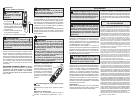
When the meter is on in any
function, the non-contact volt-
age detector will indicate with a
Red LED on the display when
an electric fi eld exceeding 90V
is detected. Place the edge of
either the jaw near the electric
fi eld.
Worklight LED ON/OFF
To turn the light on and off, press the button.
Over-fl ow indication
Any time the input exceeds the measuring range
“OL” or “-OL” is displayed.
1. Set the Rotary Dial to
posi-
tion.
2. Connect the K-type Tem-
perature Probe to the input
terminal. The positive (+)
side of Probe should be
connected to V.
3. Place the probe sensor in
the desired location.
4. The reading is displayed.