6
(b) All posts, terminals, and connectors should be cleaned to a shiny bright finish, using a wire brush
or sand paper. This should be done periodically to assure maximum conductivity between the
battery and the charger.
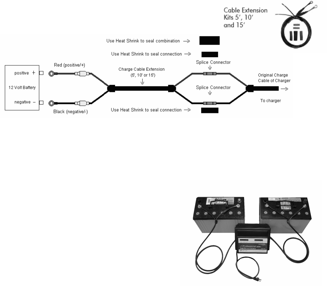
Each charge cable assembly is equipped with a temperature sensor located at the junction of each set of
ring terminals. Attempts to shorten the cables could partially disable the charger. Therefore, we
recommend that you do not make any adjustments without first consulting our technical support group
(800.742.2740). Proper cable extensions may be purchased in 5’, 10’, and 15’ lengths. See picture
below.
To connect the charger to the battery (batteries), route your charge cables from the charger to the
batteries, being cautious to avoid sharp objects, and use the supplied wire ties to hold them securely and
neatly in place.
Securely attach each charge cable independently to one 12V battery by connecting the red (positive/+)
lead ring terminal to the positive (+) battery post and the black (negative/-) lead ring terminal to the
negative (-) battery post. See picture below:
(-) (+) (-) (+)
The charger pictured
is a Professional Series
Dual Pro, which has two
independent 15 amp outputs.
Connect a heavy duty UL approved extension cord to the power cord of your charger and then plug the
extension cord into a nearby 120VAC GFI protected (Ground Fault Circuit Interrupt) outlet.
You should now observe a red LED indication on each bank of the charger representing each individual
battery being charged. The voltage of each battery will reflect the number of LED indicators illuminated.
When charging is complete, remove the extension cord from the 120VAC outlet first and then unplug the
charger.


