


- 2 -
English
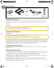
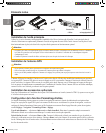
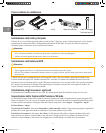
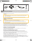
What’s Included
GPS antenna main unit screws (4) wiring harness hook and loop
fasteners (2)
Installing the main unit
Use the screws or the hook and loop fasteners (similar to Velcro
®
) provided to mount the main unit in the vehicle. Select a location
that allows you to access the unit’s SD card slot. Be sure to place the unit horizontally (flat) and secure it completely for best
performance.
Caution
• Do not install the unit where it will be exposed to direct sunlight, excessive heat or humidity, dust, spills, or liquids. Use only the
screws provided. If you use the wrong screws, you could damage the unit.
• Check for cables or other parts underneath the floor mat before cutting the floor mat.
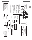
Installing the GPS antenna
Caution
• Do not paint the antenna. This will impair or disable signal reception.
• Remove any object or accumulated snow, etc., from the top of the antenna. It will reduce reception strength.
• Do not pull the cord when removing the antenna or adjusting its position. This can cause a short or snap the wires.
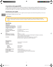
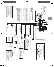
The GPS antenna can be installed either inside or outside the vehicle. It should be placed horizontally for best GPS reception. The
GPS antenna must have a clear view of the sky. If you install the antenna inside the vehicle, place it close to a window; GPS signals
can pass through glass but not through metal. Refer to the image on the next page for recommended places to install the antenna.
Place the GPS antenna on a metallic surface, such as the roof of your vehicle, for best reception.
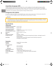
Installing optional accessories
For information on installing the optional FM traffic receiver (such as the GTM 10), refer to the Installation Guide included with
the traffic receiver.
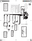
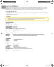
Setting Up Dead Reckoning
Dead Reckoning (DR) allows the navigation system to continue to provide navigation guidance even if it loses GPS reception. After
you connect the pink wire and start the navigation sytem, you must set up Dead Reckoning before it will work correctly. From the
Menu page of the navigation system, touch Settings > Navigation > Dead Reckoning Setup > Settings.
Odometer Wave Type—select Square Wave or Sine Wave. Determine the proper setting by contacting the vehicle manufacturer
or by using an oscilloscope. Square Wave is the most common type.
Reverse Light Polarity—select High or Low. Contact the vehicle manufacturer for polarity or check with a voltmeter. Set to
High (most common) if a positive, high voltage is detected when the reverse lights are illuminated. Set to Low if no voltage or low
voltage is detected when the reverse lights are illuminated.
190-00493-50_0A.indd 2 2/13/2006 8:31:46 AM