


LM2350E-X
PAGE4OF4
PUMP
DISASSEMBL
Y
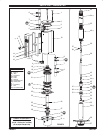
NOTE: All threads are right hand. Refer to Figure 2 (page 3). DisĆ
connect air supplyand relieve all system pressure priorto servicĆ
ing. Carefullyremovethe parts,inspect fordamage, nicksor excessive
wear and determine if any parts will need replacement.
1. Using a 7/8" wrench, unthread and remove (11) adapter and (13) ``O"
ring, releasing (14) muffler housing.
2. Using a 7/16" wrench, remove (31) nuts.
3. Remove four (1) bolts, (2) upper cap and (3) gasket.
4. Remove (10) cylinder, containing (4) sleeves and (7) spools.
5. Using (1) bolt, push (7) spools and (4) sleeves out ``sleeve" end of
(10) cylinder.
6. Remove (18) retaining ring, (19) washer and (21) piston.
7. Remove (25) dowel pin, releasing (23) piston adapter.
8. Remove (22) lower cap and (3) gasket.
9. Using a1-3/4"wrench, unthreadandremove (28)bushing,with(26
and 27) ``O" rings.
10. Clamp (34) extension tube horizontally in a vise. Unthread and reĆ
move (30) baseand (33)gasket. NOTE: Remove(29)rod sealonly
if replacement is necessary.
11. Pull up on (36) piston rod to reveal (38) cotter pin.
12. Remove (38) cotter pin and (37) connecting pin,releasing (36) pisĆ
ton rod.
13. Using (36) pistonrod, pushdown on(39)connector untilit bottoms.
14. Remove (54) retainer ring.
15. Push (55) primer up into (56) primer tube.
16. Lightly wedgea flatbladescrewdriver between(55) primerand(56)
primer tube, so (55) primer unthreads with (56) primer tube.
17. Insert a 5/16" diameter rod thru the cross holes in (56) primer tube
and use the rod to unthread and remove (56) primer tube.
18. Remove (46)spacer,(51) gasketand(52)valveseatfrom(56) primĆ
er tube.
19. Remove (47 - 50) foot valve assembly from (53) primer rod.
20. Remove (47) retaining ring, releasing (48) ``U" cup. NOTE: Do not
remove (49) guide spacer unless replacement is necessary.
21. Remove (45) guide washer.
22. Clamp (40) lower suction tube horizontally in a vise. Unthread and
remove (34) extension tube and (35) gasket.
23. Using a 7/32"diameter rodin thecross holein (39)connectorand a
9/16" wrenchon the flatsof (41) plunger, unthreadand remove(39)
connector from (41)plunger. NOTE:Do notdamage theo.d. of(41)
plunger in any way.
24. Using a 7/16" wrench on flats of (44) adapter anda 1/4" wrench on
flats of (53) primer rod, unthread and remove (53) primer rod.
25. Clamp on flats of (41) plunger and, using a 1/4" wrench on flats of
(44) adapter, unthread andremove (44) adapter, releasing (43)ball
and (42) ball stop.
PUMP
REASSEMBL
Y
NOTE: Thoroughly clean and lubricate all seals. Replace all soft
parts with new ones included in the repair kit. Note: Refer to the ilĆ
lustration (figure 2, page 3) for ``U" cup lip seal direction.
1. Assemble (42) ball stop and (43) ball into (41) plunger, securing
with (44) adapter. NOTE: Torque(44) adapter to50 -70 ft lbs(67.8
- 94.9 Nm).
2. Assemble (53) primer rod to (44) adapter, using wrenches on flats
to tighten.
3. Thread (39) connector to (41) plunger, using a 7/32" diameter rod
thru the cross hole to tighten.
4. Assemble (49) guide spacer and (48) ``U" cup into (50) valve body,
securing with (47) retaining ring. NOTE: Assemble chamfered corĆ
ner of (49) guide spacer into (50) valve body first.
5. Assemble (45) guide washer and (47 - 50) foot valve assembly
onto (53) primer rod.
6. Assemble (46) spacer, (51) gasket and (52) valve seat onto (53)
primer rod.
7. Thread (55) primer onto (53) primer rod, securing with (54) retainer
ring.
8. Thread (56) primer tube to (40) lower suction tube and tighten.
NOTE: Torque (56) primer tube to 65 ft lbs (88.1 Nm).
9. Assemble (36) piston rodto (39) connector, securing with (37) conĆ
necting pin and (38) cotter pin.
10. Assemble (35) gasketand (34)extension tubeto (40)lower suction
tube and tighten. NOTE: Torque (34) extension tube to 65 ft lbs
(88.1 Nm).
11. Assemble (33) gasket into (30) base and assemble (30) base to
(34) extension tube. Clamp (30) base horizontally in a vise and
tighten (34) extension tube. NOTE: Torque (34) extension tube to
65 ft lbs (88.1 Nm).
12. Assemble (29) rod seal over (36) piston rod and into (30) base.
13. Push up on (55) primer, exposing (36) piston rod.
14. Assemble (26 and 27) ``O" rings to (28) bushing and thread (28)
bushing into (30) base and tighten until it bottoms. NOTE: During
assembly of (28) bushing, be careful not to damage (27) ``O" ring.
15. Assemble (22) lower cap and (3) gasket to (30) base.
16. Assemble (24) ``O" ring to (23) piston adapter and assemble (23)
piston adapter to (36) piston rod, securing with (25) dowel pin.
17. Replace (20)``U" cupson(21) pistonandassemble (21)pistononto
(23) piston adapter, securing with (19) washer and (18) retaining
ring.
18. Replace (5) ``O" rings on (4)sleeves and assemble(4) sleeves into
(10) cylinder. NOTE:Assemble each sleeveinto the end ofthe cylĆ
inder nearest the exhaust hole.
19. Replace (6 and 9) ``O" rings and (8) ``U" cups on (7) spools and asĆ
semble (7)spools into(10)cylinder fromtheopposite endas the(4)
sleeve went in.
20. Assemble (10) cylinder onto the pump, being careful when sliding
over the lips of (20) ``U" cups. NOTE: Be sure (3) gasket is seated
properly.
21. Replace (3) gasketon (2)upper capand assemble(2) uppercap to
(10) cylinder.
22. Assemble (1) boltstopump, securingwith (31)nuts. NOTE:Torque
(31) nuts to 80 in. lbs (9 Nm).
23. Replace (13) ``O" ring on (11) adapter.
24. Assemble (15) foamliners and (16)edge trimsto (14)muffler housĆ
ing.
25. Assemble (14) muffler housing to (10) cylinder, securing with (11)
adapter. NOTE: Torque (11) adapter to 80 in. lbs (9 Nm).
TROUBLE SHOOTING
If the pump will not cycle or will not deliver material.
• Be certain to check for non-pump problems including kinked, reĆ
strictive or plugged inlet/outlet hose or dispensing device. DepresĆ
surize the pump system and clean out any obstructions in the
inlet/outlet material lines.
• Check all seals, including track gaskets.
• Check direction of ``U" cup lips.
PN97999-700
T