


Page 15
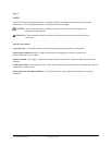
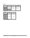
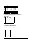
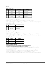
Table 8 Frequency Test:
Step Source Level Reading
1 5.600KHz 100mV rms 5.598 to 5.602
2 56.00KHz 100mV rms 55.98 to 56.02
3 560.0KHz 100mV rms 559.8 to 56.02
4 5.600MHz 250mV rms 5.598 to 5.602
5 56.00MHz 1V rms 55.98 to 56.02
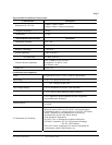
Calibration
Calibrate the meter once a year to ensure that it performs according to specifications.
Perform calibration at an ambient temperature of 23ºC ±2ºC and relative humidity of 75% or less
Calibration for the Model 61-320, 61-322 and 61-324:
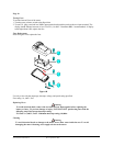
1. Disconnect the test leads and turn the meter off. Remove the test leads from the front terminals.
2. Position the meter face down. Remove the screws from the case bottom.
3. Lift the end of the case bottom until it gently unsnaps from the case top at the end nearest the LCD.
4. Loosen the screws that hold the circuit board in place and gently lift the board to access the calibration pots.
DO NOT REMOVE THE SCREWS.
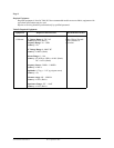
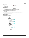
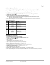
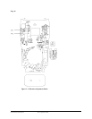
(A) DCV Calibration (Adjust VR1 – Figure 3)
5. Set the circuit board rotary switch “arrow” to the “V
” position of circuit board.
6. Set the output of DC calibrator for 300.0V ±0.02% and connect to VΩHz and COM input terminals
on the meter.
7. Using a small flat-tipped screw driver, adjust the potentiometer VR1 until the display reads 300.0 or 299.9
8. Disconnect the DC calibrator from the meter.
(B) ACV Calibration (Adjust VR2 – Figure 3)
9. Set the circuit board rotary switch “arrow” to the “V
” position of circuit board.
10. Set the output of AC calibration for 300V 50Hz and connect to VΩHz and COM input terminals on
the meter.
11. Using a small flat-tipped screw driver, adjust the potentiometer VR2 until the display reads 300.0 or
299.9
12. Disconnect the AC calibrator from the meter.
Form number TM61320-2-4 Rev 2 September 2002