


Page 13
Testing the Capacitance Function
The meter measures capacitance by charging the capacitor with a known direct current, measuring the
resultant voltage, and calculating the capacitance. If the same capacitance is measured on an impedance
bridge, a different reading may result. This variance is likely to be greater at higher frequencies.
To verify the accuracy of the capacitance measuring function, do the following:
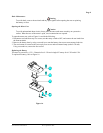
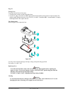
1. Apply the capacitor to the VΩHz and COM inputs on the meter for steps 1 through 7 in Table 4.
2. Turn the rotary switch to
.
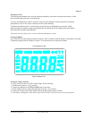
3. Compare the reading on the meter display to the reading in Table 4.
Note: The meter selects the proper range automatically. Each measurement takes about one second
per range, 5mF takes about 4.5 seconds.
4. If the display reading falls outside of the range shown in Table 4, the meter does not meet specification.
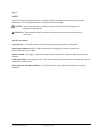
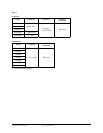
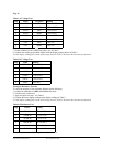
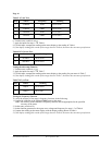
Table 4 Capacitance Test:
Step Source Reading
1 5.800nF 5.682 to 5.912
2 58.00nF 56.82 to 59.12
3 580.0nF 568.2 to 591.2
4 5.800µF 5.682 to 5.912
5 58.00µF 56.82 to 59.12
6 580.0µF 568.2 to 591.2
7 5.800mF 5.682 to 5.912
Checking the Diode Test Function
To check the diode test function, do the following:
1. Connect the calibrator to the VΩHz and COM inputs on the meter.
2. Turn the rotary switch to
.
3. Apply 0.500V DC.
The meter display should read approx. 0.500V dc.
4. Apply a 50Ω resistor to the meter, the built-in beeper alarms.
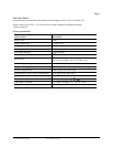
Testing the Milliamp (mA) Function (for 61-322 and 61-324)
To verify the accuracy of AC current measurement functions, do the following:
1. Connect the calibrator to the mA and COM inputs on the meter.
2. Turn the rotary switch to mA
.
3. Apply the inputs for steps 1-4 in Table 5.
4. For each input, compare the readings on the meter display to the reading in Table 5.
5. If the display reading falls outside of the range shown in the Table 5, the meter does not meet specification.
Form number TM61320-2-4 Rev 2 September 2002