


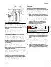

Installation
313597E 13
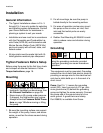
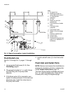
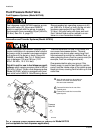
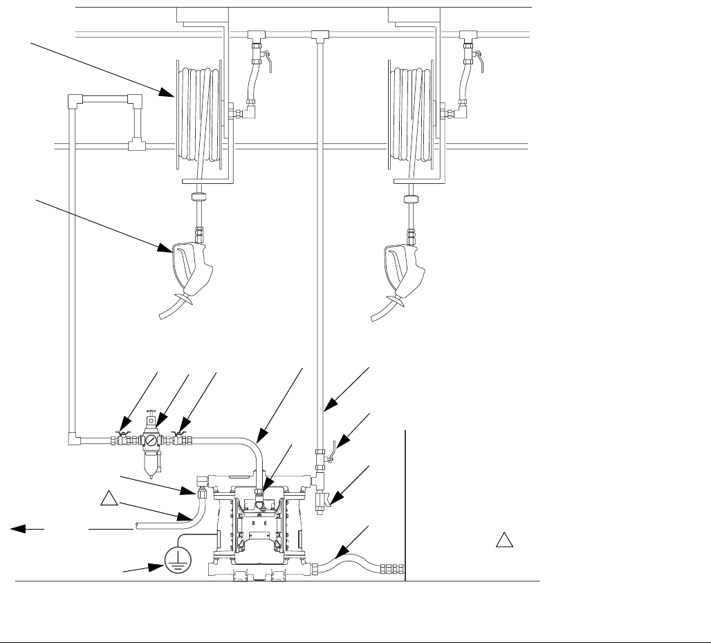
FIG. 5. Fuel dispense, typical installation
Key:
A Air supply line
B Bleed-type master air valve
(required for pump)
C Air filter/regulator assembly
D Air inlet
E Master air valve (for accessories)
G Grounded, flexible fluid supply line
H Fluid drain valve (required)
J Fluid shutoff valve
K Grounded, flexible fluid outlet line
P Hose reel
R Ground wire (required, see page 8
for installation instructions)
S Pressure relief valve (required to
limit fluid outlet pressure to 50 psi
[350 kPa, 3.5 bar])
X Fuel dispense valve
A
B
C
D
E
G
H
J
K
P
X
S
R
Fluid from the relief valve must be
piped back to the supply tank.
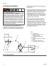
1
1
ti14220b
Pipe to
supply
tank