


H
ORIZON
NAVIGATION
5NavMate® Installation Manual
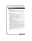
3.3 Verify system starts and update software
1) Make sure ignition is OFF.
2) Connect wire harness to controller and video cable to controller and display unit.
3) Turn on ignition.
4) Insert the CD-ROM into the controller. NavMate will update its software. DO NOT
TURN OFF THE IGNITION WHILE NAVMATE IS UPDATING.
5) Verify that NavMate powers-up correctly.
NOTE: The Display should be connected before power is turned on.
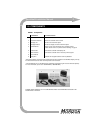
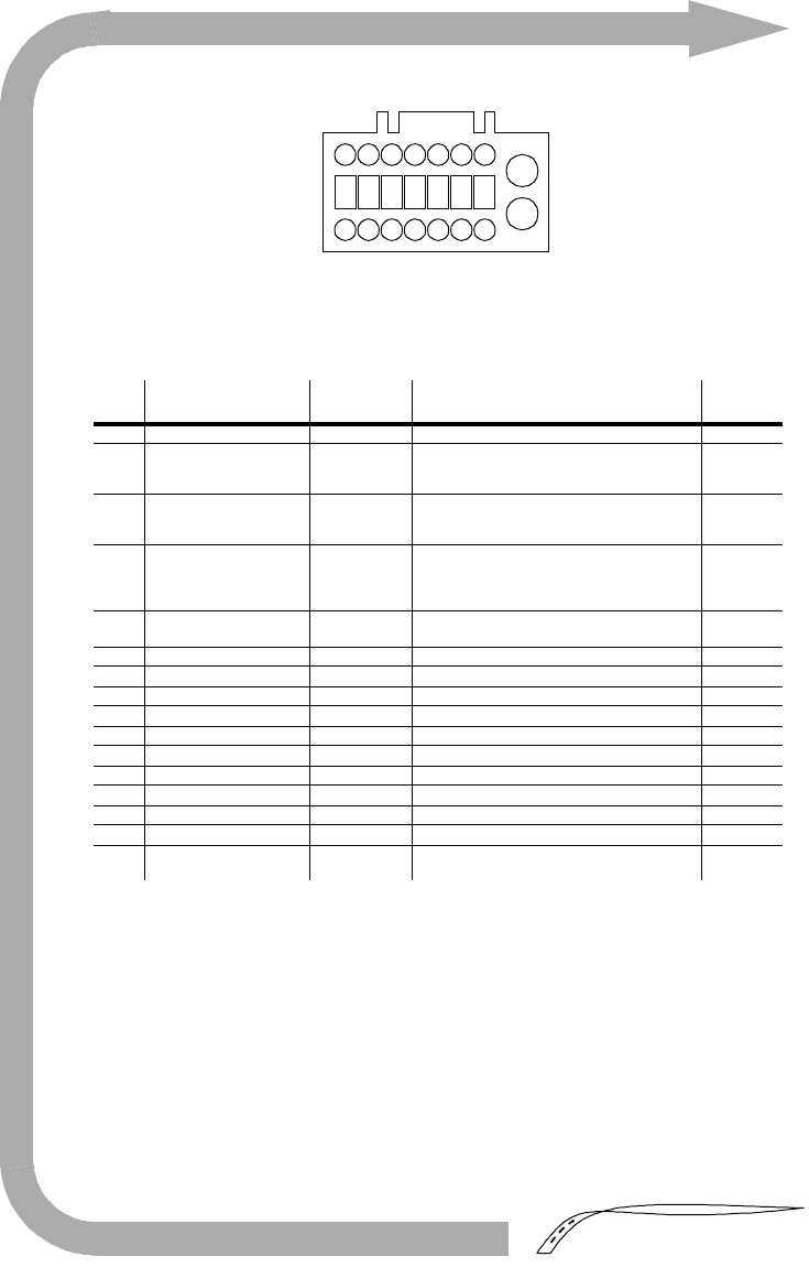
TABLE 2. Signal/Power
No. Signal/Power Wire Color Requirements
Typical
location
1 Ground (battery minus) Black battery minus Chassis
2 Reverse gear signal Light Green +13.8V DC nominal (when vehicle in reverse)
Low level voltage VL max: 1.0 VL (min.)
High level voltage VH min.: 7.0 VH (min.)
Backup
light
3 Ignition signal Pink +13.8V DC nominal (when ignition on)
Low level voltage VL max: 1.0 VL (min.)
High level voltage VH min.: 7.0 VH (min.)
Fuse
block
4 Vehicle speed signal
(sine wave)
Yellow Input pulse frequency: ˜0Hz to 2.5 KHz
Input voltage range: -13 to +26 Vmax
Low level voltage VL max: 0.9 VL (max)
High level voltage VH min.: 4.0 VH (min.)
PCM
5 Vehicle speed signal
(square wave)
Green/White Input pulse frequency: 1 Hz to 200 Hz
Input voltage range: -13 to +26 Vmax
PCM
6 Not used - - -
7 Not used - - -
8 Not used - - -
9 Not used - - -
10 Not used - - -
11 Not used - - -
12 Not used - - -
13 Not used - - -
14 Not used - - -
15 Not used - - -
16 System power source
(battery plus)
Red +13.8 V DC nominal, 3 Amp (min.) Fuse
block
10
12 15
14
13119
2345678
16
1
CONTROLLER CONNECTOR
(WIRE HARNESS VIEW)