


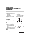
VBN2, VBN3 CONTROL BALL VALVE/ACTUATOR ASSEMBLIES
3 62-0197—04
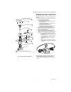
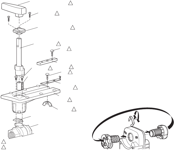
Fig. 6. Valve assembly exploded view.
OPERATION AND CHECKOUT
Once both the mechanical and electrical installations are
complete:
1. Cycle the actuator to verify that the direction of rota-
tion suits the control sequence.
2. If the rotation direction is incorrect:
a. For 2-position control actuators: Remount actu-
ator on the bracket.
b. For floating control actuators: Reverse two con-
trol signal wires (CW/CCW).
c. For analog control actuators either:
(1) Reposition reverse/direct acting switch, or
(2) Remount actuator on the bracket.
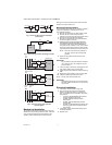
3. If the control scheme requires fail-safe operation,
ensure that, upon removal of power, the valve
rotates to the desired position.
4. Spring return actuators are factory-configured for
A-port normally-closed fail-safe operation. To
change this to normally-open, remove and reinstall
the actuator in the opposite orientation as follows:
(a) Loosen the shaft coupling bolt using a 10
mm wrench.
(b) Loosen all other mounting bolts connect-
ing the actuator to the mounting bracket,
and set aside.
(c) Remove the actuator from the valve
shaft.
(d) Move the actuator shaft coupling to the
opposite side of the actuator, as displayed
in Figure 7.
Fig. 7. SCSA Mounting
For detailed actuator information, see Honeywell forms:
— 63-2209 ML6161,ML7161 Product Data Sheet.
— 63-2607 S05,S10,S20 Series Actuator Product Data
Sheet.
M29526
VALVE BODY
VALVE STEM
COUPLER
WING NUT
MOUNTING
PLATE
ANTI-ROTATION
BRACKET
BOLT
STEM ASSEMBLY COVER
SCREWS (2)
HANDLE (REMOVABLE) FOR
MANUALLY ROTATING SHAFT
STEM ASSEMBLY
SCREWS (2)
STEM RETAINER PLATE
BOLT
ANTI-ROTATION
BRACKET
1
2
INCLUDED IN REPLACEMENT KIT (PART NO. 5112-11).
THIS PART USED WITH NON-SPRING RETURN ACTUATORS.
1
2
1
1
1
1
1
1
1
1
1
M27714