


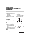

VBN2, VBN3 CONTROL BALL VALVE/ACTUATOR ASSEMBLIES
62-0197—04 2
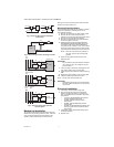
Fig. 3. Three-way ball valve flow orientation
(not to scale).
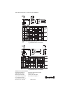
Fig. 4. Reset mixing control for discharge hot water.
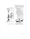
Fig. 5. Three-way mixing valve operation
with coil bypass.
Mechanical Installation
The valveshave female NPT pipe fittings and should be
sealed with an approved pipe sealant or tape. Take care
not to use excess pipe dope to avoid interfering with
operation of ball. Torque should not exceed 75 ft-lb.
See Fig. 8 and 9 for valve dimensions. Refer to actuator
literature for actuator dimensions.
Mounting Plate Adjustment
The Actuator Mounting Plate can be rotated to a different
position for installation in confined spaces. This is
accomplished as follows:
1. Remove the handle from the shaft and set it aside.
2. Remove the two screws that hold the stem
assembly to the mounting plate and set them aside.
3. Remove and set aside the stem assembly.
4. Remove and set aside the two screws that attach
the mounting plate to the valve.
5. ENSURE VALVE IS ISOLATED AND DEPRES-
SURIZED BEFORE PROCEEDING. Remove yel-
low pressure plate marked “HIGH PRESSURE”
from valve bonnet, rotate 90° or 180°, and re-install
screws using same holes in pressure plate and the
appropriate pair of tapped holes in the valve bonnet.
NOTE: Take note of the screw hole positions on
the valve. They limit the mounting plate
positions.
6. Rotate mounting plate around valve top to the
desired position.
IMPORTANT
Do not rotate the valve stem while the hold-down
ring is removed. This can change the common
port from AB to A.
7. Lower ring down to valve body and engage it in the
new position relative to the mounting plate.
8. Tighten screws to valve body securing the mounting
plate.
9. Reattach the stem assembly to the mounting plate.
10. If desired, replace the handle on the shaft.
NOTE: See Fig. 6 for valve exploded view.
IMPORTANT
After adjusting a three-way valve mounting plate,
take note whether the AB port or the A port is the
common port.
Electrical Installation
1. If necessary, remove actuator wiring cover.
2. Wire the actuator according to the appropriate
diagram provided with actuator or job specifica-
tions. For detailed actuator information, see Honey-
well literature:
— 62-0274—MS7505/MS8105 Spring Return
Actuator Installation Instructions
— 63-2632—MN6105 Floating Actuator
Product Data
— 63-2633—MN7505 Modulating Actuator
Product Data
— 63-2209—ML6161/ML6164/ML7161/ML7164
Non-spring return direct Coupled Actuators
Product Data
3. If applicable, position reverse/direct acting switch
for desired operation.
4. Replace cover.
M13737
SUPPLY
RETURN
AB PORT A PORT
B PORT
COIL
SUPPLY
RETURN
AB PORT A PORT
B PORT
COIL
MIXINGDIVERTING
B
A AB
M29517
BOILER
PUMP
VBN3
AB A
B
M19523
HEATING COIL
FULL
HEAT
5 GPM
5 GPM
2.5 GPM
5 GPM
AB A
B
PROPORTIONED
HEAT
2.5 GPM
SUP PLY
MAIN
RETURN
MAIN
5 GPM
5 GPM
AB
VB3
VB3
VB3
A
B
NO
HEAT
NO FLOW
THROUGH COIL