INSTALLATION INSTRUCTIONS
62-0197-04
VBN2, VBN3
Control Ball Valve/Actuator
Assemblies
INSTALLATION
When Installing this Product...
1. Read these instructions carefully. Failure to follow
them could damage the product or cause a
hazardous condition.
2. Check ratings given in the product data literature
and on the product to ensure the product is suit-
able for your application.
3. Installer must be a trained, experienced, licensed
service technician.
4. After installation is complete, check out product
operation as provided in these instructions.
Preparation
CAUTION
Equipment Damage Hazard.
Foreign particles like dirt and metal chips can
damage the ball seals.
Clean upstream lines prior to installation.
CAUTION
Equipment Damage Hazard.
Improper chemicals can damage the valve.
Use neither aerosol products nor petroleum-
based lubricants.
1. Clean the lines upstream of particles larger than
1/16 in. diameter. Open valves fully. Flush entire
hydronic system of contaminants (welding slag,
solder, scale, metal chips, etc.) and chemically
treat water according to local conditions prior to
operation.
2. Proceed with installation once the system specifics
(expansion/contraction of the system and its
medium as well as operating pressures) are within
tolerances.
3. Eliminate air from system.
4. Two-way valves are marked to show flow direction.
IMPORTANT
Flow arrows must point in the direction of the
flow for proper operation.
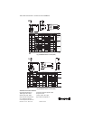
NOTE: For three-way valve mounting, see Fig. 3
through 5.
5. Stem rotation:
a. For two-way valves:
(1) Clockwise to close.
(2) Counterclockwise to open.
b. For three-way valves:
(1) Clockwise to increase B to AB flow.
(2) Counterclockwise to increase A to AB flow.
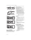
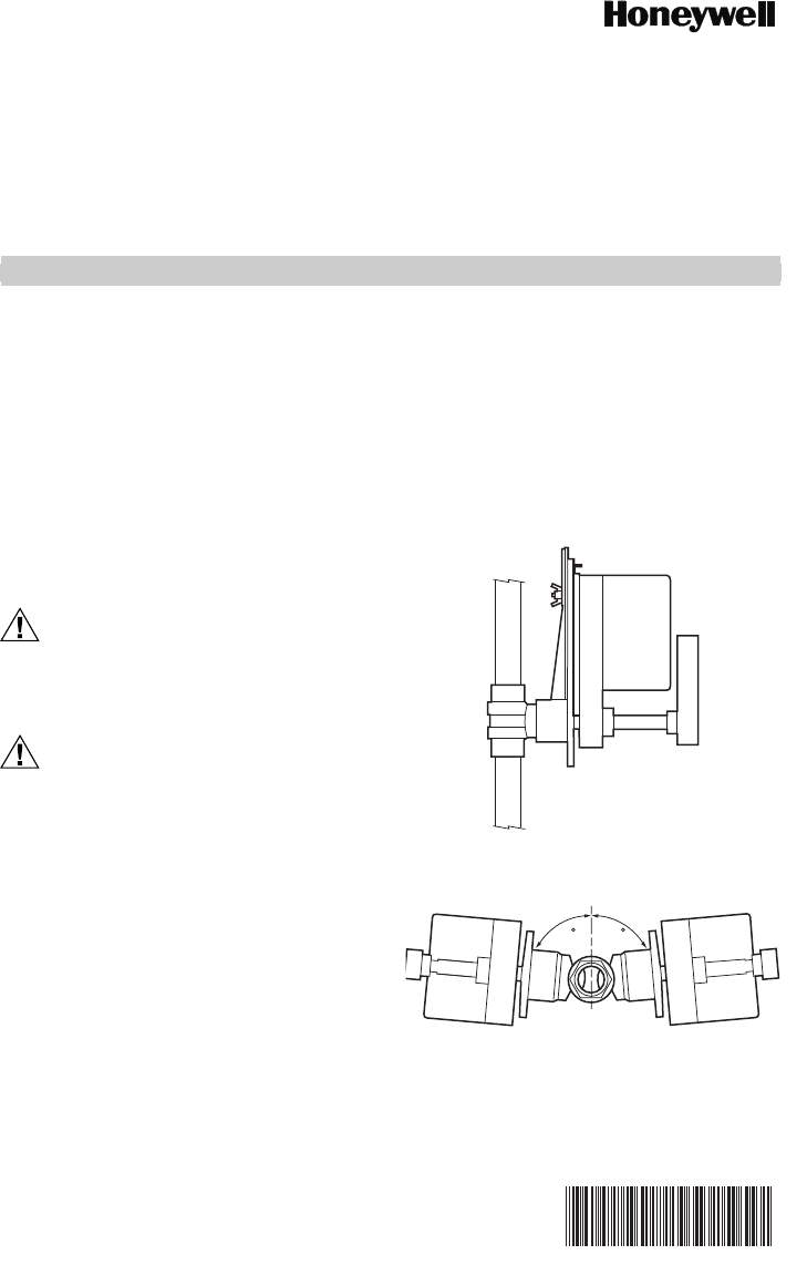
6. Valve must be mounted with the actuator/bracket
above the valve body. Do not install the valve with
the stem below horizontal or upside down. (See
Fig. 1 and 2.)
Fig. 1. Vertical valve installation.
Fig. 2. Acceptable valve angle from vertical.
M29518
85 85
M29519A


