


ML6425, ML7425 SPRING RETURN ELECTRIC LINEAR VALVE ACTUATORS
7 63-2516—07
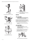
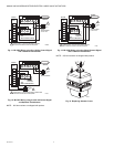
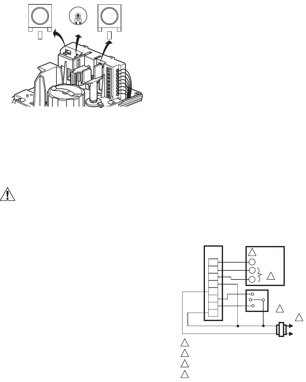
Fig. 15. Location of W1, W2, and W3 Selector Plugs.
Auxiliary Potentiometers
The 43191679 Auxiliary Potentiometers can be used as
feedback potentiometers and to provide remote indication of
the valve position. Refer to the Installation Instructions packed
with the potentiometers.
Auxiliary Switches
CAUTION
Equipment Damage Hazard.
Improper voltage will damage the auxiliary switch
beyond repair.
Use the 43191680 Dual Auxiliary Switch only with 24
Vac applications.
The 43191680 Dual Auxiliary Switch can be used on both the
ML6425 and ML7425 Electric Linear Valve Actuators.
Switching points are adjustable over the full length of actuator
stroke; for example, the switch can be used to switch pumps or
provide remote indication of any stroke position. Refer to the
Installation Instructions packed with the auxiliary switch.
OPERATION
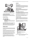
In the actuator, the drive of a synchronous motor is converted
into the linear motion of the actuator stem by using a spur gear
transmission. A button retainer clip connects the actuator stem
to the valve stem.
An integrated spring package limits the stem force to a factory
adjusted value in either direction. Installed microswitches turn
off the actuator when the specified stem force is reached.
The ML6425, ML7425 Spring Return Valve Actuators provide a
safety valve position in the event of power failure. On power
failure, the ML6425A and ML7425A extend the actuator stem;
the ML6425B and ML7425B retract the actuator stem.
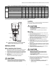
The actuators are shipped from the factory with a spring
handle retaining clip installed, so the actuator can be
connected to the valve without applying power. Remove this
clip after the actuator is installed. (Refer to the Installation
section.)
ML7425
Signal Input (+)
The analog input signal (+) range is set at the factory to 0 to 10
Vdc. Changing the position of the W2 selector plug sets the
range to 2 through 10 Vdc. Selector plugs W1, W2, and W3 are
positioned on the back side of the printed circuit board. Refer
to Fig. 15 for location of the selector plugs.
Signal Input Failure
Using the potentiometer, the actuator can be set to run to any
position in event of a signal failure (ML7420/ML7425 only).
ML6420 does not have any input signal failure jumpers or
potentiometers.
Output Signal Feedback (F)
An analog output signal (2 to 10 Vdc) that represents the actual
actuator stem position is available at terminal F. It can be used
for remote indication of the stem position. When the valve stem
is fully downward, the output signal is 10 Vdc.
When the valve stem is up, the output signal is 0 or 2 Vdc. The
output of the signal does not change when the action of the
actuator is reversed using W3. See Direction of Action.
Actuator Override
To override the control signal (for freeze protection or similar
applications), connect the 24 Vac common (T2) to either
terminal O1 or O2. Connecting to terminal O1 fully extends the
actuator stem. Connecting to O2 fully retracts the actuator
stem.
The control signal (+) is ignored when the override signal is
applied to Terminal O1 or O2. This override can be achieved
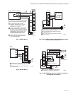
with a switch or a relay (See Fig. 16).
Fig. 16. Connections for Overriding Control Signal to Drive
ML7425 to a Specific Position.
M33047
0%
W3
100%50%
W2
W1
POWER SUPPLY. PROVIDE DISCONNECT MEANS AND
OVERLOAD PROTECTION AS REQUIRED.
F
+
0-10Vdc OR 2-10 Vdc CONTROL SIGNAL. SEE SIGNAL
INPUT (+) SECTION.
SEE OVERRIDE SECTION FOR DETAILS ON
OVERRIDE OPERATION.
2-10 Vdc FEEDBACK SIGNAL. SEE OUTPUT SIGNAL
FEEDBACK SECTION.
ML7425
WIRING
STRIP
F
+
–
T2
T1
O1
O2
TS
1
3
4
2
INPUT
(FEEDBACK)
OUTPUT
3
2
SP3T
OVERRIDE
SWITCH
4
1
L1
(HOT)
L2
–
M7906A