


ML6425, ML7425 SPRING RETURN ELECTRIC LINEAR VALVE ACTUATORS
63-2516—07 4
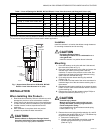
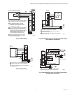
Fig. 2. Attaching Actuator to Valve Collar.
Fig. 3. Securing Actuator to Valve.
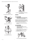
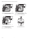
Fig. 4. Removing Actuator Cover.
Fig. 5. Removing Spring Retaining Clip and Releasing
Manual Spring Handle.
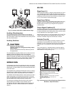
WIRING
CAUTION
Electrical Shock or Equipment Damage Hazard.
Can shock individuals or short equipment circuitry.
Disconnect power supply before installation.
All wiring must comply with local electrical codes, ordinances
and regulations. Voltage and frequency of the transformer
used with the actuator must correspond with the power supply
and actuator characteristics. Refer to Figures 6 through 13 for
connection information and typical wiring hookups.
1. Feed power and control wires through the conduit
connector located on the bottom of the actuator case
(See Fig. 6).
CAUTION
Equipment Damage Hazard.
Conduit connection or removal can break an
unsupported connector.
When removing or attaching conduit, use a wrench to
support the motor connector.
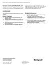
2. Using the wiring diagram in Fig. 7, connect power and
control wires. Make sure that all wiring is correct.
3. When wiring is complete, replace the cover on the
actuator (Refer to Fig. 14).
4. Apply power and control signals to the actuator.
Fig. 6. Connecting Power and Control Wiring.
M6632
M6633
M6627
M6629
M6630