


63-2493—1
8
ML6275 SPRING RETURN DIRECT COUPLED ROTARY ACTUATOR
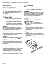
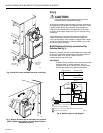
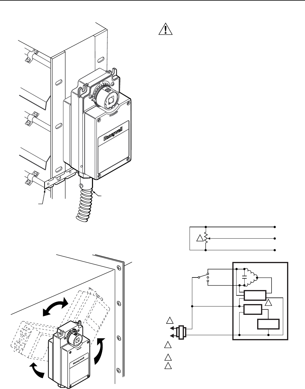
Wiring
CAUTION
Disconnect power supply before wiring to prevent
electrical shock or equipment damage.
All wiring must comply with local electrical codes, ordinances
and regulations. The ML6275 is designed for use with a Class
2 power supply. Voltage and frequency of the transformer
used must correspond with the characteristics of the motor
and those of the power supply. See Fig. 8 for a typical wiring
connection.
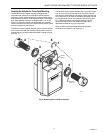
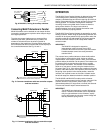
The ML6275 has an aluminum die cast housing with two
integral cast bosses on the end of the device, tapped for
1/2 in. conduit fittings. Some models are shipped with a water
seal in the conduit opening. If conduit is needed, remove the
seal before routing the cable.
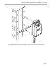
ML6275 Models with Factory-mounted Auxiliary
Switches (See Fig. 9)
ML6275C,F models have two nonadjustable line voltage rated
spdt auxiliary switches that are factory set to make common
to normally open at 12° and 82° rotation from the
counterclockwise stop. See Fig. 9.
IMPORTANT:
Actuators driving in parallel may not be synchronized
with each other. In normal operation, when all
actuators are driven to the fully open or fully closed
position, the actuators are again synchronized.
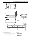
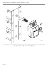
Fig. 6. ML6275 Actuator standard electrical connection.
M9384
30
0
60
500
500
90
60
30
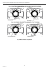
Fig. 7. ML6275 Actuator can be mounted in any position.
(NOTE: NEMA rating applies only with damper shaft in
horizontal position.)
.500
.500
30
30
60
60
90
M7231
MOUNTING
BRACKET
TO JUNCTION
BOX (UP TO
3 FT AWAY)
L1
(HOT)
L2
1
1
2
3
3
2
MOTOR
OPTIONAL
TIME OUT
POWER
SUPPLY
SPRING
CONTROL
24 VAC
OPEN
BLUE
CLOSE
YELLOW
24 HOT
RED
24 GND
BLACK
ML6275
M9954A
POWER SUPPLY. PROVIDE DISCONNECT MEANS AND OVERLOAD
PROTECTION AS REQUIRED.
TIME-OUT FUNCTION AVAILABLE WITH ML6275D,F MODELS.
500 OHM POTENTIOMETER.
FEEDBACK WIRING
ORANGE (OPEN)
TAN
GREEN (CLOSED)
Fig. 8. ML6275 typical wiring diagram.