


61-86-03-13
Page 4
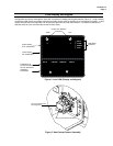
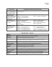
Set Up/Configuration Parameters
Configuration parameters are logically grouped and accessed using the local HMI. Actuator calibration is also
accomplished through a simple procedure using the keypad. By pressing the SETUP button on the HMI, you can step
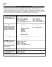
through the set up groups that contain all of the configuration parameters. The table below summarizes the configuration
parameters available within the various set up groups. Full details of all configuration parameters are found in the 11280S
Series Smart Actuator Installation, Operation and Maintenance Manual, document number 61-86-25-09.
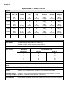
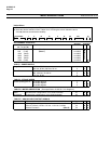
Set Up Group Configuration Parameter Selections/Settings
SET INPUT Selects various
parameters that define actuator
operation.
IN TYP – Input Actuation Type
INP HI – Input High Range Value
INP LO – Input Low Range Value
FILTYP – Input Filter Type
LPFILT – Low Pass Filter Time Constant
Direct – Actuator Rotation
Dband – Input Deadband
FsTYP – Failsafe Type
FsVAL – Failsafe Value
CHAR – Input Characterization
LDCAL – Restore Calibration Type
SET RELAY When the actuator
is equipped with optional relays,
this set up group allows you to set
relay action for various actuator
operating conditions. Contact
closure can be wired to external
annunciators or alarm points to
indicate conditions for any of the
Relay Types.
RTYPnn – Relay Type
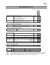
Input Range
Position Range
Deviation
Upper or Lower Limit Travel
Temperature High or Low
Motor Starts
Motor Stalled
Manual Mode
Power Up Test Failure
Input Signal Failure
Position Sensor Signal Failure
Digital Input Closure
RnnE – Relay Count Multiplier
RnnVAL – Relay Value
Rnn HL – Relay High/Low
RLYnHY – Relay Hysteresis
SET CUROUT Selects the
current (or voltage) output range
of the actuator.
CUROUT - Output Signal Range
4 – 20 mA, 0 – 20 mA,
1 – 5V, 0 – 5V,
SW E (Slidewire Emulation)
SET COMM Actuator can be
defined as a master or slave
device on a Modbus RTU RS-485
loop. Operating setpoint can be
transmitted to the actuator and
operating status can be read
when connected to supervisory
control systems.
COMM – Communications Parameters
ADDRES – Device Address
BAUD – Baud Rate
XmtDLY – Response Delay
DBLBYT – Floating Point Data Format
SET DIGINP Selects digital
input action upon contact closure.
DIGINP – Digital Input State
Endpos – End Position Value
SET DISPLA Selects desired
decimal places and engineering
units for local display.
DECMAL – Decimal Point Location
EUNITS – Units Display
UNITS – Display Units
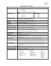
CAL INPUT, MTR, CURENT If needed, calibration of the actuator input, motor position and actuator output can be
performed using the local keypad and display.
Continued on next page
⇒