


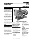
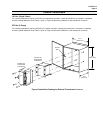

61-86-03-13
Page 2
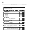
Features (continued) Health Monitoring
Operation
• Control Signals – 0/4 to 20 mA,
0/1 to 5 Vdc, 0 to 10 Vdc, Digital
remote setpoint (RS485 Modbus
RTU protocol).
• Output Signals – 0/4 to 20 mA,
0/1 to 5 Vdc and slidewire
emulation.
• Manual Operation – All 11280S
series actuators are supplied with a
manual handwheel to operate the
actuator when power is not
available.
• Auto-Manual – electric handswitch
with auxiliary contacts indicating an
"Out-of-Auto" position is available
for local electric control.
• RS485/Modbus RTU
Communication – Simple and
easy to use Modbus RTU
communication is standard with all
11280S actuators allowing
seamless networking of Honeywell
control products.
• Auxiliary Outputs – Two types of
auxiliary outputs can be specified,
SPDT switches or
electromechanical relay outputs.
Relay outputs can be programmed
to output alarm conditions, provide
control of other equipment, or
indicate status.
• Alarm Functions – Alarms may be
assigned to relay outputs or may be
accessed through Modbus. Alarms
can be triggered from stall,
temperature limits, motor cycle
count, out of automatic mode,
digital input, position, input failure,
position sensor failure, power up
failure, and more.
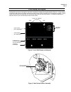
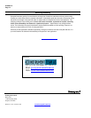
• Local HMI Configuration – An
integral keypad and high intensity
display is available for non-intrusive
local configuration of the actuator
(Figure 2).
• Configuration Security –
Password protection is provided,
allowing users to lock out some, all,
or no groups of setup parameters to
prevent tampering.
• Factory Calibration – Factory
calibration is stored in non-volatile
memory and can be restored via
the local HMI at any time.
• Direction of Rotation – Direction
of rotation on increasing input
signal is programmable.
• Split Range Operation – Split
range is programmable and
infinitely adjustable.
• Digital Input Override – A digital
input is provided and is
programmable to provide override
of all other input signals as an
emergency override of control. The
digital input can be programmed to
drive the actuator open, closed,
remain in-place, or to a user-
specified position on contact
closure.
• Failsafe – When input signal
exceeds high or low range limits
(or input signal failure), the
actuator can be programmed to
drive open, closed, remain in-
place, or drive to a user-specified
position.
Construction
• Enclosure – Rugged, industrial
grade enclosure.
• Low Maintenance – Simple-
proven design means high
reliability/low maintenance.
• Output Shaft Hardware – All
11280S series actuators are
supplied with an adjustable radius
crank arm. Optional linkage kits
are available.
• Limit Switches – Two end-of-
travel electric limit switches are
supplied as standard equipment
with all 11280S series actuators.
• Warranty – Exceptional warranty.
A standard feature on all 11280S
actuators accumulates information
about actuator operation. This
information then can be used to
evaluate and determine predicted or
scheduled maintenance periods. The
parameters that are monitored include:
accumulated stall time, thermal
operating rating of the actuator
exceeded, number of motor starts in a
region of motor travel, total travel and
current actuator travel.
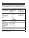
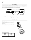
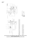
Non-Contact
Position Sensing
Honeywell 11280S series actuators
implement a variable inductance, non-
contact position sensor mounted directly
to the actuator output shaft providing
precision position sensing from 0 to 90
degrees, (Figure 3). This technology
eliminates maintenance items such as
wipers, bearings, as well as static
friction, hysteresis and electrical noise
over a wide range of demanding
environmental conditions.
Slidewire Emulation
The Slidewire Emulation Circuit (SEC)
emulates the proportional voltage
output of a typical slidewire through a
high impedance circuit. The voltage
output is proportional to the supply
voltage and shaft position. A non-
contact position sensor is used to
determine shaft position in place of the
slidewire.