


13
WARNING: Be careful when removing the fuel rail test port fitting. The fuel rail may be pressurized. Always allow the
engine to cool before performing this operation. Fuel sprayed onto hot engine components may start a fire.
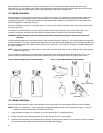
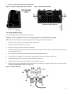
2. Remove the cap over the fuel rail test port on the front of the driver’s side fuel rail.
3. Bleed off the fuel pressure in the rail by covering the test port with rags and depressing the schraeder valve.
4. Remove the schraeder valve with a valve core tool.
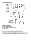
5. Install the fuel safety switch on the test port using the 4AN x 1/8” NPT Female Adapter (19).
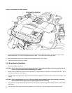
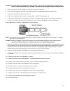
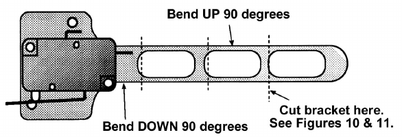
6. Install the microswitch (22) on the throttle body, so that the microswitch is triggered by the throttle linkage at wide-open
throttle. Figure 9 shows the microswitch installation and Figure 10 shows the suggested mounting configuration.
Figure 9 Microswitch Template—Suggest Mounting Configuration
NOTE: The microswitch may be mounted to the bracket in a variety of positions and on either side of the bracket. The bracket
may be bent to suit the application.
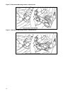
WARNING: Binding or dragging of the throttle linkage will create a potentially dangerous stuck-throttle condition.
Ensure that the microswitch does not interfere with the normal throttle linkage operation.
7. Adjust the microswitch to trigger at wide-open throttle, by adjusting the microswitch’s position to ensure the actuation arm of
the microswitch “clicks” at the same point the throttle linkage reaches wide-open throttle against the throttle stop (Figure 9).
Ensure the throttle and switch can reach activation position shown in Figure 9 by using the accelerator pedal. Have an
assistant slowly press the pedal to the floor while you listen for the “click” of the microswitch.
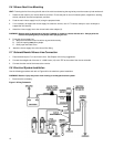
8. Install the NOS arming switch (23) inside the car, within easy reach of the driver.
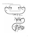
9. Install the 30 amp Relay (24) in the engine compartment near the battery. The relay’s orange wire should reach the battery
(+) terminal.
10. Connect the orange relay wire to the battery (+) terminal.
11. Connect one wire from each solenoid together. Join the solenoid wires to the blue relay wire.
12. Connect the open second solenoid wire to either terminal on the fuel pressure switch (18).
13. Connect the open terminal on the fuel pressure switch to the ground.
14. Connect the green relay wire to either terminal on the microswitch.
15. Connect the open terminal on the microswitch to the ground.
16. Connect the red relay wire to the middle (#2) terminal on the arming switch (23).
17. Connect the (#1) terminal on the arming switch to the switched 12 volt power source.
18. Connect the (#3) terminal of the arming switch to the ground.
19. Reconnect the battery.