


8 XL-FW232-02
REBUILDING PROCEDURES continued
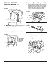
Adjust the Fifth Wheel Locks:
1. Using a ratchet with 1/2˝ Allen wrench, tighten the
adjustment screw (
20) in the throat in the fifth wheel,
by turning the screw clockwise until tight.
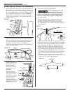
2. Check that the kingpin on the lock tester is square to
the swinging lock (
6) and that the stationary lock is
square to the kingpin. If not square, align the kingpin
and/or stationary lock as necessary and retighten the
adjusting screw.
3. Tighten the lock nut (
19) on the stationary lock.
4. Loosen the adjustment screw (
20) by turning counter-
clockwise 1
1
⁄2 turns. The locking mechanism is now
properly adjusted.
Check that the secondary lock operates freely.
Check the operation of the fifth wheel by locking and
unlocking it several times.
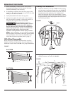
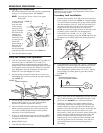
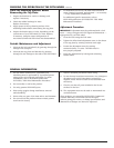
CHECKING THE OPERATION OF THE FIFTH WHEEL
With the fifth wheel turned upright, it will
function as follows:
When the swinging lock (6) is open, the release handle
(
16) will be in; the plunger (17) will extend into the throat
area so that the step in the plunger is visible in the throat,
as shown in
FIGURE 18, and the secondary lock release
handle (
18) will be out, with the handle lug disengaged
from the top plate casting.
Fifth Wheel Coupling:
As the lock tester is coupled to the fifth wheel, the swinging
lock closes, pushing the plunger (
17) back, and the release
handle (
16) out.
As the swinging lock closes, the secondary lock spring will
move the secondary lock into the closed position behind
the swinging lock, and move the release handle inward.
When properly locked, the locking plunger (
17) will be
visible as shown in
FIGURE 18.
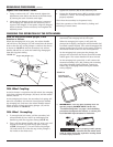
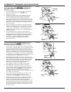
Fifth Wheel Uncoupling:
1. To uncouple the lock tester, pull the secondary lock
release handle (
9) out, raise it up and engage the
handle lug with the top plate casting (
FIGURE 19).
2. Then, pull the release handle (16) out, raise it up, and
engage its handle lug with the top plate casting
(
FIGURE 15 on page 7). This will retract the plunger
(
17) and hold it in so that the step in the plunger is
not visible in the throat area.
Step in the plunger (17)
FIGURE 18
3. As the kingpin on the lock tester is pulled out
(rearward), the swinging lock (
6) will open.
When the swinging lock opens, it will push the
plunger back slightly, causing the release handle (
16)
to extend outward slightly. This action disengages the
release handle from its notch in the casting, allowing
the release handle to move to the locked position.
As the swinging lock opens past the plunger, the
plunger will extend into the throat area and become
visible again. The release handle will move inward.
As the swinging lock opens fully, it will contact the
retracted secondary lock (
10), pushing the secondary
lock release handle slightly outward, causing its
handle lug to disengage and allowing the handle
to drop slightly.
4.
IMPORTANT: If the top plate assembly does not
operate properly,
DO NOT USE IT. Review the
“Troubleshooting Hints” on page 2 and rebuilding
procedures throughout this manual, or contact your
local HOLLAND representative for assistance.
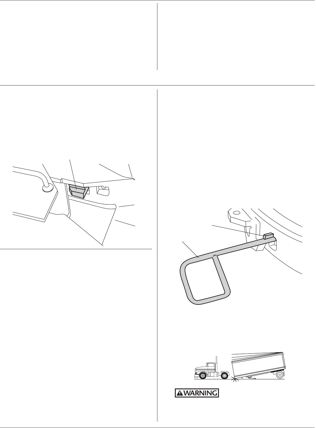
Failure to properly install, operate,
or maintain this fifth wheel could
result in tractor and trailer separation causing death
or serious injury to others.
9
Secondary lock
release handle lug
FIGURE 19
➠