


10 XL-FW232-02
TAB ON
SWING LOCK
LOCK ARM
WITH STEP
END
NO
ADJUSTMENT
BLOCK
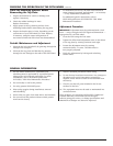
ALTERNATIVE “SECONDARY LOCK INSTALLATION”
FIGURE A
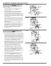
ADJUSTMENT
BLOCK
.25
B
3/16 ± 1/16
A
FIGURE B
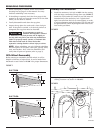
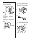
For fifth wheel models ORIGINALLY equipped with a
tab on the swing lock and a step end on the lock
arm, follow the instructions below and refer to
FIGURE A, at right.
1. Coat the lock pin hole in the secondary lock (10) with
Never-Seez
®
(supplied with kit). DO NOT use a
substitute lubricant.
2. Install the secondary lock release handle (
9) into the
casting. Install the secondary lock onto the handle.
Install a cotter pin (
8) in the handle and spread it.
Drive the secondary lock pin (
3) through the holes in the
casting and secondary lock, and secure with a cotter pin
(
2). Install a grease fitting (25) in the lock pin so that the
fitting faces the side, and will be accessible from the left
side of the tractor.
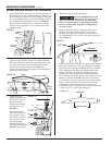
3. Move the secondary lock handle to the closed position.
Check the location of the end of the secondary lock in
relation to the swinging lock. It should be 3/16˝ (0.188˝)
±1/16˝ (0.06˝) from point
A on the swinging lock (see
FIGURE B) when the secondary lock is resting against the
casting at point
B.
4. If the secondary lock is not in the current position,
install a secondary lock adjustment block (
36) as shown
in
FIGURE B. Move the adjustment block until proper
adjustment is achieved, then weld the adjustment block
in position, as shown in
FIGURE B. After welding,
check the dimension and for proper operation of
the secondary lock.
ADJUSTING
BLOCK
PRE-INSTALLED
FIGURE C
ADJUSTMENT
BLOCK
.25
B
3/16 ± 1/16
A
FIGURE D
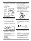
For fifth wheel models ALREADY equipped with an
adjustment block, follow the instructions below
and refer to FIGURE C, at right.
1. Pre-install the secondary lock (10) in the closed position
in the casting. Complete
Steps 1, 2, and 3 before installing
the spring, release handle, and the secondary lock pin.
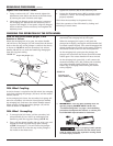
Align the lock pin holes and rotate the secondary lock up
against the adjustment block. Check the location of the
end of the secondary lock in relation to the swinging lock.
It should be 3/16˝ (0.188˝) ±1/16˝ (0.06˝) from point
A on
the swinging lock (see
FIGURE D) when the secondary lock
is resting against the adjusting block at point
B.
2.
If the dimension is less that 1/8˝ (0.125˝), mark the area
where the secondary lock made contact with the adjusting
block. Remove the secondary lock, then place a bead of
weld on the adjusting block, where the secondary lock
makes contact with the adjusting block, and grind
smooth. Do not weld on the secondary lock.
After welding, re-check as in
STEP 1, in this section.
3.
If the dimension is more that 1/4” (0.25”), mark the
area where the secondary lock makes contact with the
adjusting block. Remove the secondary lock, then grind
on the adjusting block.
CAUTION: A small amount of
grinding on the adjusting block results in a large
movement of the secondary lock. After grinding, re-check,
as in
STEP 1, in this section.
C. After a final check of the dimension, coat the lock pin
hole in the secondary lock (
10) with Never-Seez
®
(supplied with kit). DO NOT use a substitute lubricant.
D. Install the secondary lock release handle (
9) into the
casting. Install the secondary lock (
10) onto the handle.
Install a cotter pin (
8) in the handle and spread it.
Drive the secondary lock pin (
3) through the holes in the
casting and the secondary lock, and secure with a cotter
pin (
2). Install a grease fitting (25) in lock pin so that the
fitting faces the side and will be accessible from the left
side of the tractor.