


307158 9
Service
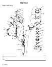
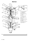
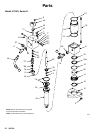
Disassembly (continued – refer to Fig. 3)
CAUTION
When removing the displacement pump, hold it
securely. The pump is heavy and could fall off the
motor.
5. Disconnect the displacement pump from the
motor, as explained in your separate pump manu-
al.
6. Place the hydraulic motor in a bench vise.
7. Push or lightly tap the piston (49) up as far as
possible.
NOTE: The tie rod nuts (3), socket screws (8), cap–
screws (24), and retainer (32) are fastened with Loc-
titer TL–242. Heat may be used sparingly to soften
adhesive sealant during disassembly.
8. For Models 217022, 217338, 262818, and
24W139, loosen, but do not remove, the four tie
rod nuts (3) and the nuts (B) on the hydraulic tube
(48).
For Model 235345, you need to remove the cap
screws (21), the drip pan (26), the drip cover (31),
and machine screw (42) before loosening the tie
rod nuts. Then remove the four tie rod nuts (3).
Loosen the nuts (B) on the hydraulic tube (48) and
loosen the tie rods (35).
9. Remove the motor from the vise and lay it in a
pan.
10. Remove one detent assembly: retaining plug (28),
o-ring (25), spring (29), ball guide (27) and ball (7).
If the ball or other parts stick in the upper housing
(40), turn the motor over and tap lightly. Do not
allow the parts to fall into the motor. Repeat the
procedure for the other detent assembly.
11. Remove the tie rods (35), but do not remove the
crown nuts (22).
12. Remove the socket screws (8) and the end cap
(44). Pull the stop plug (43) from the upper hous-
ing (40).
13. Unscrew the top and bottom compression nuts (B)
on the hydraulic tube (48). Rotate the upper hous-
ing (40) and remove the tube, being careful not to
damage the flare (A). Allow the oil to drain from
the motor into the pan.
CAUTION
With the tie rods removed, the assembly may sepa-
rate at the joints between the cylinder (39) and the
upper and lower housings (40 and 41).
14. Rock the upper housing (40) to work it free and lift
it about 3 inches off the cylinder (39). The cylin-
der can stay in the lower housing (41).
15. Hold the trip rod (36) with an adjustable wrench on
the flats of the rod, and remove the top hex nut
(20) from the trip rod.
16. Remove the upper housing (40).
17. Remove the trip rod guides (34), compression
springs (38) and valve spool (37) from the upper
housing. Inspect the bearing inside of the guide
(51) in place. If bearing is damaged replace item
51.
NOTE: Inspect the trip rod (36) above the shoulder for
damage. There must be no reduction in diameter.
Replace if necessary.
18. Pull the trip rod and piston from the lower housing
(41) and cylinder (39). Place the piston flats (49) in
a vise; tighten the vise on the flats of the piston.
Use a face spanner to remove the retainer (32).
Remove the trip rod (36) from the piston (49).
19. Remove the trip rod locknut (9) and piston stop
(33). If the piston is replaced, remove the spring
(55) to use in the new piston.
20. For Models 217022 and 217338, place the lower
housing (41) on top of vice jaws. Pinch the adapter
plate (14) in the jaws. Twist and remove. Inspect
the bearing (30) and wiper (18) for wear. Replace if
necessary.
21. Turn lower housing over and remove the seal (23)
and backup seal (23a).
22. For Models 235345, 262818, and 24W139, re-
move the bearing (45), packings (23), and o-ring
(12, Model 235345 only).