


307158 11
Service
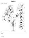
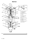
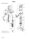
Reassembly (Refer to Fig. 4)
NOTE: Model 217022 uses one seal (23) and a back-
up seal (23a).
1. Lubricate the seal(s) (23) with hydraulic oil. Install
them in the lower housing (41) with the lips facing
up toward the top of the motor.
2. For Models 217022 and 217338, install the o-ring
(12*) onto the adapter (14). Install the adapter (14)
into the lower housing (41), making sure it seats
properly. For Model 235345, install the o-ring (12)
onto the lower housing (41).
3. Place the piston flats in a vise. Install the spring
(55) inside the piston (49). The compression rings
(19) must be positioned with the joints about 180_
opposed. Be sure the o-ring (26) is in place on
Model 235345.
4. Install the piston stop (33) and locknut (9) on the
trip rod. Torque the nut to 117–123 in-lb (13.2–13.9
N.m). Slide the trip rod (36) into the piston (49).
Apply thread sealant to the retainer (32) threads.
With the piston flats in a vise, tighten the retainer
until it is flush or below the piston surface. This is
important to prevent the retainer from backing out
during operation and damaging the motor.
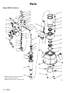
NOTE: For Models 235345, 262818, and 24W139, set
base (2) on workbench during reassembly. For Models
217022 and 217338, place adapter (14) in vise jaws
and lower housing (41) on top of jaws.
5. Install the o-ring (13) onto the cylinder (39). Install
the cylinder (39) into the lower housing (41).
6. Install the trip rod and piston into the cylinder (39)
and lower housing (41) so the piston is recessed at
least 1 inch (25 mm) from the top of the cylinder.
7. If the bearing and guide (51) was removed, install
it on the upper housing (40) with the three screws
(24) (apply thread sealant).
8. Hold the flats of the trip rod with an adjustable
wrench and install the upper housing (40). The trip
rod will protrude from the top.
9. Slide the lower trip rod guide (34) and spring (38)
onto the trip rod. Install the spool (37) with the
detent at the top. Install the top spring (38) and
guide (34) on the trip rod. Install the top hex nut
(20). Torque the nut to 82–88 in-lb (9.3–9.9 N.m).
10. Remove the adjustable wrench. Seat the upper
housing (40) onto the cylinder (39), so the tube
fittings align with those on the lower housing.
Reinstall the hydraulic tube (48) and loosely
tighten the compression nuts. See the Parts
Drawing for your motor.
11. Replace the o-ring (11) on the stop plug (43). Seat
the plug into the upper housing (40).
12. Install the end cap (44), using thread sealant on
the socket screws (8).
13. Lubricate the threads of the tie rods (35) and install
them with lockwashers (1). If the crown nuts (22)
were removed, reinstall them and torque them
onto the rods to 70–80 ft-lb (95–108 N.m).
14. For Models 217022, 217338, 262818, and
24W139, take the motor out of the vise jaws and
lay it on its side. Install the lower plate (10).
NOTE: For Model 217022, align the point of adapter
plate (10) in the same direction as the fluid tube (16).
15. For Models 217022, 217338 and 262818, apply
thread sealant to the lower threads of the tie rods
(35) and torque the tie rod nuts (3) to 70–80 ft-lb
(95–108 N.m).
For Model 235345 and 24W139, torque tie rods
into base, apply thread sealant, then torque the tie
rod nuts (3) to 70–80 ft–lb (95–108 N.m).
16. With the motor on its side, install one detent
assembly: the ball (7), guide (27) with the concave
surface toward the ball, spring (29), o-ring (25*)
and retaining plug (28). Torque the plug to
152–158 in-lb (17.2–17.9 N.m). Repeat for the
other side of the motor.
17. For Model 235345, slide the drip cover (31) onto
the piston (49) up to the o-ring (30). Install screw
(42) into the piston. Attach the drip pan (26) to the
base using screws (21).
18. Snugly tighten the compression nuts on the hy-
draulic tube (48) and torque to 60–80 ft-lb (81–108
N.m).
19. Install the motor on the displacement pump. Re-
connect all fluid lines. Be sure the ground wire is
connected before operating the pump.