


Installation
14 Apollo GX50/60/65 Installation Manual
ELECTRICAL CONNECTIONS
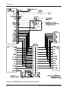
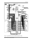
Wiring necessary for installation of the GX50/60/65 includes the rear panel electrical
connections and the antenna cable placement. The 15 and 37 pin d-sub connectors and coax
connector(s) may be wired before or after being installed in the mounting frame. The
recommended connecting wire size for the connectors is 20 to 24 AWG. Wiring diagrams are
included on pages 18 through 24.
POWER
The GX60/65 requires two power connections, one for the GPS navigation side of the unit, the
other for the comm. Make the power connections to the unit using 20 AWG wire.
The GPS navigation power input is internally fused at 3 amps. A separate 2 amp (maximum)
circuit breaker or fuse should be installed for downline overload or short circuit protection.
The comm power input (GX60/65 only) is internally fused at 7 amps. A separate 5 amp (maximum)
circuit breaker or fuse should be installed for downline overload or short circuit protection.
Note: Circuits should be protected in accordance with guidelines in AC 43.13-1A,
chapter 11, section 2, paragraph 429.
Warning
When connecting power to the GX unit, reversing the polarity of the connection
will blow the internal fuse. The internal fuse is soldered onto the circuit board
and requires repair at the factory.
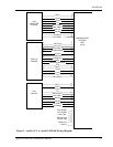
AVIONICS OUTPUTS
The GX50/60/65 includes avionics outputs for CDI/HSI indicators, autopilot, and
annunciators. These outputs are to be connected as appropriate for the particular installation.
The CDI/HSI outputs may be connected to a dedicated CDI or HSI or to a shared indicator
using an appropriate switching relay. The avionics outputs available are listed in the Avionics
Outputs specification on page 35. Connect the annunciator outputs to lamp indicators as
described in the specifications. The minimum connections required for different installations
are listed in the System Configurations on page 4.
If a switching relay is used to make connections to a shared CDI/HSI, it should be a minimum
of an eight pole relay box with an appropriate selector switch with annunciation. The ILS
enable signal (see Figure 8 and Figure 11) from a connected ILS receiver can be connected to
automatically switch the indicators back to the nav receiver when an ILS frequency is
selected.
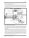
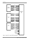
SERIAL INTERFACE
The GX50/60/65 includes two RS-232 serial ports for making optional connections. The serial
ports can be used for connecting to such devices as the Apollo SL40 comm, a moving map
display, multi-function display, autopilot, VHF Nav/Com, Fuel Air/Data computer, or an
altitude encoder/converter. Serial output connections should be limited to no more than three
external units.
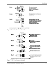
When making connections to the GX50/60, use a three-conductor shielded cable (for two-way
serial communication) or a two-conductor shielded cable (for one-way serial communication).
Make RxD, TxD, and signal ground connections to the 37-pin connector. Connect the shield(s)
to the rear of the mounting frame. The shield leads must be <1.25 inches. See Figure 5.
Complete serial interface specifications are included in Appendix E.