


190-00133-02 Rev B 3-8
3.3.3.8 Side Lobe Suppression
1. Set the SLS / ECHO toggle switch to the OFF position.
2. Adjust the RF level on ATC-1400A to MTL so that the XPDR%REPLY is 90%.
3. Raise the RF level to 3 dB above the MTL.
4. Set the SLS / ECHO thumb wheel switch to 0dB.
5. Flip the SLS / ECHO toggle switch to the ON position. The GTX 320 % Reply shall have an average reading
of 1% or less.
6. Raise the RF level on the ATC-1400A to MTL +50 dB. The GTX 320 % Reply shall have an average reading of
1% or less.
______ < 1% Reply (Average Reading)
3.3.3.9 External Suppression
With the unit replying to interrogations, apply a positive external suppression pulse of up to 100 microseconds
and with a voltage amplitude of greater than 8.0 volts. The unit must suppress the replies to any interrogations
received during the time of the suppression pulse.
______ OK
3.3.3.10 External Altittude Encoder Inputs
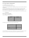
1. Set the digital oscilloscope to the following settings:
PARAMETER SET POINT
EXT TRIG CH 2 (XMTR Detected Video)
CH 2 VERTICAL SENS 20MV/DIV
HORIZONTAL SWEEP 5µS
DELAYED SWEEP CENTER ON FIRST PULSE
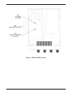
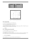
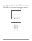
2. Set the XPDR MODE switch on the ATC-1400A to position C. The oscilloscope shall display the P1 and P3
pulses similar to Figure 3-3. ______ OK
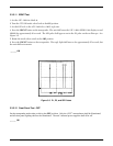
3. Rotate each of the four rotary switches on the GTX320 under test through at least one complete turn, stopping
on zero. The unit shall not transmit any code information as evidenced by a change in the P1 and P3 pulse
patterns. The XPDR CODE digital display on the ATC-1400A test set shall indicate 0000. ______ OK
4. Rotate the mode select switch on the GTX320 under test to the ALT position. ______ OK