


190-00133-02 Rev B 3-6
3.3.3.4 Minimum Trigger Level Adjustment (MTL)
1. Set the PRF thumb wheel switches to 500 Hz.
2. Set the ATC-1400A XPDR MODE switch to position A.
3. Reduce the RF level on the ATC-1400A test set until the nominal reply rate is 90%. The RF level (MTL) shall
be -69 dBm or less.
4. Set the ATC-1400A XPDR MODE switch to position C. The nominal reply rate should remain at 90%.
5. If the nominal reply rate is less than 90%, then increase the RF level until the nominal reply rate is 90%. The
RF level shall be less than -69 dBm and shall not deviate greater than 1dB from the MTL in Mode A.
6. Increase the RF level to 50 dB above MTL. The reply rate displayed on the ATC-1400A shall be at least 90%.
________ > 90% Reply Rate
3.3.3.5 Reply Pulse Characteristics
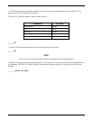
1. Set the oscilloscope to the following settings:
PARAMETER SET POINT
EXT TRIG CH 2 (XMTR Detected Video)
CH 2 VERTICAL SENS 20mV/Div
HORIZONTAL SWEEP 100ns
DELAYED SWEEP CENTER ON FIRST PULSE
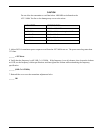
2. Configure the ATC-1400A front panel controls to the following settings:
PARAMETER SET POINT
XPDR MODE MODE C
PRF 500 Hz
RF LEVEL -50 dBm
SLS / ECHO OFF
FREQUENCY/POWER TOGGLE SWITCH F
1
/P
1
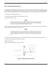
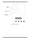
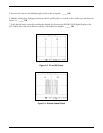
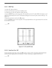
3. Set the GTX 320 mode control select knob to the ON position. The reply pulse will be visible on the oscillo-
scope as shown in Figure 3-2. The pulse shape must possess the qualities listed in the table below.