


Page 3-4 G3X Installation Manual – GMU 44
Revision A 190-01115-01
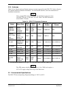
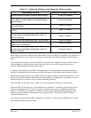
Table 3-7. Required Distance from Magnetic Disturbances
Disturbance Source Minimum Distance from GMU 44
Electric motors and relays, including servo motors 10 feet (3.0 meters)
Ferromagnetic structure greater than 1 kg total
(iron, steel, or cobalt materials, especially landing
gear structure)
8.2 feet (2.5 meters)
Ferromagnetic materials less than 1 kg total, such
as control cables
3 feet (1.0 meter)
Any electrical device drawing more than 100 mA
current
3 feet (1.0 meter)
Electrical conductors passing more than 100 mA
current [(must be twisted shielded pair if within 10
feet (3.0 meters)]
3 feet (1.0 meter)
Electrical devices drawing less than 100 mA current 2 feet (0.6 meter)
Magnetic measuring device (e.g. installed flux
gates, even if unpowered)
2 feet (0.6 meter)
Electrical conductors passing less than 100 mA
current [(must be twisted shielded pair if within 10
feet (3.0 meters)]
1.3 feet (0.4 meter)
Ensure that any electrical conductor that comes within 10 feet (3.0 meters) of the GMU 44 is installed as a
twisted shielded pair, not a single-wire conductor. (If possible, the shield should be grounded at both
ends.)
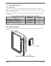
Use nonmagnetic materials to mount the GMU 44, and replace any magnetic fasteners within 0.5 meter
with nonmagnetic equivalents (e.g. replace zinc-plated steel screws used to mount wing covers or
wingtips with nonmagnetic stainless steel screws).
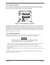
In general, wing mounting of the GMU 44 magnetometer is strongly preferred. Fuselage mounting is
strongly discouraged because of numerous potential disturbances that interfere with accurate operation.
Mechanical mounting fixtures for the GMU 44 must be rigidly connected to the aircraft structure. Use of
typical aircraft-grade materials and methods for rigid mounting of components is acceptable, so long as
adequate measures are taken to ensure a stiffened mounting structure.
Align the GMU 44 mounting rack to within 3.0° of the aircraft level reference in pitch and roll.
Align the GMU 44 mounting rack’s forward direction to within 0.5° in heading of the aircraft forward
direction (longitudinal axis). If it is not possible to guarantee this accuracy, installation alignment to
within 2.5° in heading is acceptable in combination with a post-installation heading alignment of the
aircraft to a precise heading to determine and set a heading offset. The heading offset procedure is
described in Section 8.3.4.
It is strongly preferred that the GMU 44 alignment is within 0.5° of the aircraft longitudinal axis, rather
than using the heading offset procedure.