


7
Installation
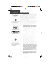
Mounting the
Receiver
If a problem is found, try altering the location of the
unit or wiring. Often moving the antenna a few feet away
from the source of interference will solve the problem.
When a suitable configuration is found, a permanent
installation should be made. Select the mounting location
according to your preferences. Keep in mind that from this
mounting location cables will be routed to the antenna and
to the GPS unit.
1. Once a suitable mounting location has been
determined and tested, secure the antenna mount at
the desired mounting location.
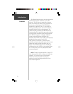
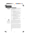
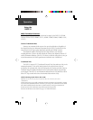
2. Make sure the DGPS 53 is aligned properly to avoid
thread damage. Thread the DGPS 53 onto the
antenna mount and hand tighten clockwise until
snug (Fig. 1). Do not overtighten.
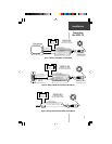
3. Align the notches on the power/data cable and
DGPS 53 connector and push the connector in until
it seats. Turn the locking ring clockwise until the
power/data cable is firmly locked into position.
4. Route the power/data cable from the DGPS 53 to the
GPS unit. Excess cable may be shortened or coiled
together and secured in an inconspicuous location. If
additional cable is needed you may use GARMIN’s
optional 60’ cable (010-10284-00) or similar 24
AWG shielded wiring. The entire length of the
power/data cable should not exceed 150’ (45.7m).
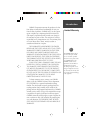
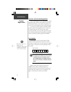
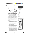
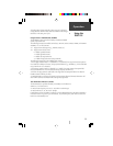
Three common sources of interference for DGPS
units are:
Radar
ABOVE- OK
BELOW- OK
EMI
3'
VHF Radio Antenna
Radar
EMI (Electromagnetic Interference) from engine components
Power/Data
Cable &
Connectors
Antenna
Mount
When routing the power/data
cable, try to avoid:
• Sharp edges which may cut the
cable
• Routing the cable parallel to
other power lines
• Excessively twisting, straining or
bending the cable
Figure 1: Mounting
the DGPS 53