


8
Installation
Connecting the
DGPS 53
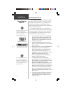
Connecting the DGPS 53
The final step in installing the DGPS 53 is to connect
the receiver’s DATA IN, DATA OUT, REMOTE ON/OFF
and GROUND (Return) lines to your chartplotter or PC.
The DGPS 53 is designed to transmit/receive data at
4800-19200 baud (bits per second), which is suitable for
use with most devices and PCs.
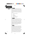
For reliable communication, it is essential that the
DGPS 53 and the receiving device share the same ground.
This ground connection acts as the (current) Return line.
It is recommended to wire the unit to it’s own circuit to
avoid interference from other electronics.
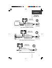
1. You may reference Figures 3 or 4 on the following
page for the wiring: Connect the BLUE (Data Out)
wire from the DGPS 53’s power/data cable to the
DATA INPUT line of the chartplotter or to pin 2 on
the DB9 (pin 3 on DB25).
2. Connect the BROWN (Data In) wire to the DATA
OUTPUT line of the chartplotter or pin 3 on the DB9
(pin 2 on DB25).
3. Connect the BLACK (-) wire to the GROUND wire of
the chartplotter or pin 5 on the DB9 (pin 7 on
DB25). If the BLACK wire is already connected to
the same ground terminal as the GPS unit, no
additional connection is required (unless a separate
RETURN line is provided by the GPS unit).
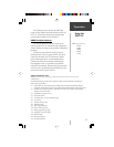
4. Connect the RED (+) wire from the power/data
cable to a 8-35 VDC power source.
5. If a remote power switch is being installed,
reference Figure 5 for wiring the switch. This will
allow the DGPS 53 to remain connected to a power
source, but manually powered on and off.
Otherwise, if the receiver is being wired to a circuit
which is already switched, (with the chartplotter for
example) connect the WHITE wire to the same place
as the BLACK wire. When the BLACK and WHITE
wires are combined, the DGPS 53 will turn on/off
when power is applied/removed to the RED (+) and
BLACK (-) wires.
6. If one-pulse-per-second (PPS) output is being used,
connect the YELLOW (+) and BLACK (-) wires to
your desired device inputs. See page 18 for more
information on PPS.
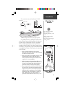
If the DGPS 53 is being connected to
a PC, a DB9 or DB25 serial
connector (normally female) will be
needed. Check with a PC or
electronics supplier for this item.
Some non-GARMIN devices may
have a separate data line labeled
“RETURN”, “DATA GROUND” or
“DATA -”. If one of these lines exist,
connect the BLACK wire from the
power/data cable to it.
1
4
6789
2
3
5
14
7
25
13
1
2
3
DB9 Female Serial Connector
DB25 Female Serial Connector