


190-00266-01 GPS 15H & 15L Technical Specifications Rev. D
Page 8
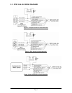
2 GPS 15H & 15L WIRE DESCRIPTIONS AND WIRING DIAGRAMS
The GPS 15H-F & 15L-F use an eight-contact flex circuit LIF (low insertion force) connector. The GPS
15H-W & 15L-W use an eight-pin JST connector (mating wire harness included). See section
1.5.1.3.
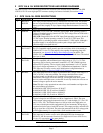
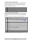
2.1 GPS 15H & 15L WIRE DESCRIPTIONS
Pin # Signal Name Description
1 BACKUP
POWER
This input provides external power to maintain the real-time clock. This enables
the user to provide backup power if needed for longer than the on-board backup
battery provides (roughly 21 days). Input voltage must be between +2.8 and +3.4
VDC.
2 GROUND Power and Signal Ground
3 POWER GPS 15L: +3.3 to +5.4 VDC (±100 mV ripple) input. Peak operating current is
100 mA. Nominal operating current is 85 mA. This voltage drives an LDO with a
nominal 3.0 VDC output.
GPS 15H: Unregulated 8.0 to 40 VDC input. Peak operating current is 40 mA @
12 VDC input. Nominal operating current is 33 mA @ 12 VDC input. This
voltage drives a switching regulator with a nominal 3.3 VDC output. Although a
regulated supply is not required, the peak-to-peak voltage ripple on this line
should be kept to less than 100 mV.
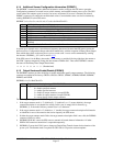
4 PORT 1
DATA OUT
Serial Asynchronous Output
RS-232 compatible output normally provides serial data which is formatted per
NMEA 0183, Version 2.0. This output is also capable of outputting phase data
information; see
Appendix B: Binary Phase Output Format for details. The
NMEA 0183 baud rate is selectable in the range of 300 to 38400 baud. The default
baud rate is 4800.
5 PORT 1
DATA IN
First Serial Asynchronous Input
RS-232 compatible with maximum input voltage range of -25 < V < 25. This
input may also be directly connected to standard 3 to 5 VDC CMOS logic that
utilizes RS-232 polarity. The low signal voltage requirement is < 0.6 V, and the
high signal voltage requirement is > 2.4 V. Minimum load impedance is 500 Ω.
This input may be used to receive serial initialization/ configuration data as
specified in section
4.1 Received NMEA 0183 Sentences.
6 RF BIAS This input allows the user to supply an external RF bias voltage in the range of 4
VDC to 8 VDC to the active antenna. The voltage should be from a clean,
regulated supply and should be well isolated from potential sources of
interference. The supply should not share RF current paths with other system
devices such as microprocessors or other RF circuits. By default, the unit uses an
internal voltage to power the active antenna.
Note: This pin is only operational on units whose serial numbers are higher than
the serial numbers given below:
010-00240-01 GPS 15H-W serial no. 81301857
010-00240-02 GPS 15L-W serial no. 81408976
010-00240-11 GPS 15H-F serial no. 81901632
010-00240-12 GPS 15L-F serial no. 82001471
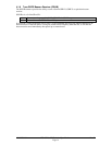
7 PPS One-Pulse-Per-Second Output
Typical voltage rise and fall times are 100 ns. Impedance is 250 Ω. The open
circuit output voltage toggles between the low (0 V) and the high (3.3 V for 15H
and 3.0 V for 15L). The default format is a 100 ms wide active-high pulse at a
1 Hz rate, with the pulse width configurable in 20 ms increments. Rising edge is
synchronized to the start of each GPS second. This output provides a nominal 450
mVp-p signal into a 50 Ω load. The pulse time measured at the 50% voltage point
will be approximately 15 ns earlier with a 50 Ω load than with no load.
8 PORT 2
DATA IN
Second Serial Asynchronous Input
This input may be used to receive serial differential GPS data formatted per
RTCM SC-104 Recommended Standards For Differential Navstar GPS Service,
Version 2.2 (see section
4.5 for more details).
Table 2: GPS 15H & 15L Wire Descriptions