


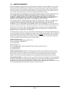
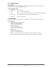
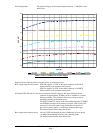
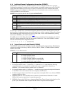

Noise Figure/Gain: The total noise figure on the external antenna must be ≤ 7 dB. Refer to the
table below.
10.0
11.0
12.0
13.0
14.0
15.0
16.0
17.0
18.0
10.0 15.0 20.0 25.0 30.0 35.0 40.0
Gain (dB)
SNR (dB)
NF=1.3dB NF=2.3dB NF=3.3dB NF=4.3dB NF=5.3dB NF=6.3dB NF=7.3dB
Table 1: Gain vs. SNR for Given Noise Figure
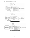
Properly bias the antenna from an on-board source or an external source:
Bias voltage from on-board source: GPS 15H supplies 3.3 VDC to the center conductor of the MCX
female, relative to the connector shell ground.
GPS 15L supplies 3.0 VDC to the center conductor of the MCX
female, relative to the connector shell ground
In both the GPS 15H and 15L, the source resistance of the DC supply to the center conductor of the
connector is approximately 10 Ohms, which is included as a current
limiting resistance. This resistance allows the receiver to survive
momentary shorting of the antenna port.
The GPS 15H and 15L sensors with serial numbers between 27700000
and 28099999 can detect if the antenna is shorted. GPS 15H and 15L
sensors no in the serial number range listed above do not have a
provision to protect against a continuously shorted antenna port.
The antenna must not draw more than 60 mA.
Bias voltage from external source: 4.0 to 8.0 VDC bias through the series combination of an on-board
~10 Ohm current limiting resistance and a Schottky diode.
The antenna must not draw more than 60 mA.
190-00266-01 GPS 15H & 15L Technical Specifications Rev. D
Page 7