


29
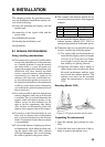
Final preparation
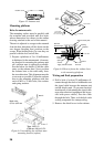
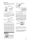
1. Place the antenna housing cover on the
housing. Loosely fasten the four fixing
bolts on the cover.
Fixing
holes
Scanner housing
cover
Pinning
hole
Figure 6-15 Fastening the antenna
housing cover
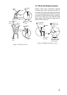
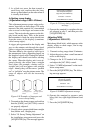
2. Apply grease to the two slot pins. Using a
wooden hammer to prevent damage to
paint, insert slotted pins into the pinning
holes until the pin head is flush with the
scanner housing surface.
Radiator
bracket
Ship’s
bow
Slotted pin
Face in
stern direction.
Figure 6-16 How to insert slot pins
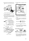
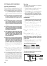
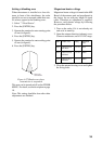
3. Now is the time to fix the radiator to the
radiator bracket. Apply anticorrosive seal-
ant (silicone sealant) to hatched areas, to
prevent corrosion. See the figure below.
Apply silicone sealant into threaded holes
on the scanner radiator. Remove the cap
on the radiator bracket and orient the ra-
diator bracket as shown in Figure 6-13.
Apply grease to the O-ring and set it to the
center of the radiator bracket. Coat the ra-
diator fixing bolts with silicone sealant.
Fasten the radiator to the radiator bracket
with the FURUNO logo on the radiator fac-
ing ship’s bow.
Waveguide
Groove
Note: Apply anticorrosive
sealant to hatched areas,
antenna radiator bottom
view of XN8 type radiator.
Figure 6-17 How to coat radiator with
silicone sealant for XN8 type radiator
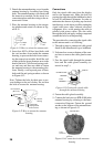
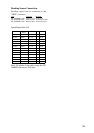
Flat washer
Spring washer
Hex head bolt
(M8 x 30)
Radiator bracket
Coat bolts with
silicone sealant.
Scanner
radiator
O-ring
Apply silicone sealant
into threaded holes.
Note: Apply anticorrosive sealant
to hached areas, antenna bracket
for XN12A type radiator.
Figure 6-18 Fastening the radiator to the
radiator bracket
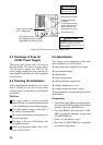
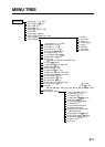
4. Open the antenna housing cover and fix the
stay as shown in Figure 6-19.
5. One end of the cable with 15-, 9- and 7-
way plugs has already been connected to
RTB-9100 inside the scanner housing.
Mate the 15- and 9-way plugs with jacks
J812 and J811 on the transceiver module,
respectively. Connect the 7-way plug to
jack J701 on the MP Board. Secure the
cable between RTB-9100 and J701 with the
cable tie as shown in Figure 6-19.
Cable
tie
J812
J811
Stay
MP Board
Fasten ground
wire here.
Figure 6-19 Antenna unit, cover opened
6. Fasten the ground wire (black) of the sig-
nal cable to the chassis as shown in Figure
6-19.
7. Loosely fasten the antenna housing cover.
You will tighten the fixing bolts after con-
firming magnetron heater voltage.