


5
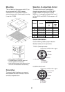
Maintenance
Self test 1
The unit performs an internal self-check in
the following sequence each time power is
turned on.
1. LEDs CR7 to CR10 blink twice every 2
seconds.
2. ROM and RAM are tested.
3. LED CR6 blinks every second for normal
operation. If an error is detected during
the test, the corresponding LED is turned
on.
• When CR7 is on, ROM is defective.
• When CR8 is on, RAM is defective.
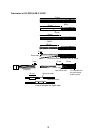
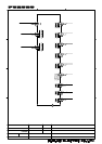
Self test 2
The test requires an external loop to check
I/O. Follow the steps below to carry out the
test.
1. Set the DIP switch #4 of S1 to the ON
position.
2. Temporarily disconnect input and output
connectors J2 and J4.
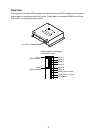
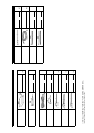
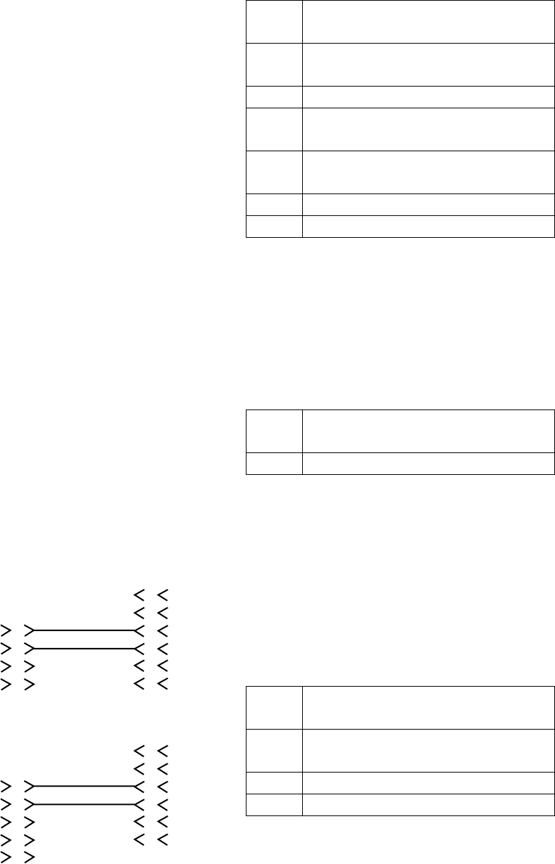
3. Construct a pair of short connector
assemblies as below.
1
2
3
4
1
2
3
4
5
6
RS422_OUT_A
RS422_OUT_B
For J4, J5, J6 ,J7 and J8
For J9
J2
J2
XH4P
XH6P
NC NC
NC
NC
GND
GND
RD_H
RD_C
1
2
3
4
5
1
2
3
4
5
6
RS422_OUT_A
RS422_OUT_B
XH5P
XH6P
NC
NC
NC
NC
NC
GND
GND
RD_H
RD_C
Short connector assy
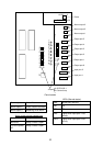
4. Connect the XH6P-XH4P short connector
assy. between J2 and J4.
5. Confirm that each LED lights according
to equipment status as follows:
CR2 Lights when receiving NMEA data
from J2.
CR4 Lights when sending NMEA data
to J4 thru J9.
CR6 Blinks every second.
CR7 Lights when ROM error is
detected.
CR8 Lights when RAM error is
detected.
CR9 Lights when SIO error is detected.
CR10 Normally off.
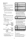
5. Remove the connector from J4 and plug
it into J5, J6, J7 and J8 successively,
confirming that CR2 and CR9 light as
below for each port. Then, remove the
XH6P-XH4P short connector assy., plug
in the XH6P-XH5P short connector assy.
between J2 and J9, and confirm that CR2
and CR9 light as below.
CR2 Lights when receiving NMEA data
at J2.
CR9 Lights when SIO error is detected.
6. Remove the XH6P-XH5P short
connector assy. Plug in the XH6P-XH4P
short connector assy. between J3 and J4,
J5, J6, J7 and J8 successively. Confirm
that LEDs light or blink as below.
Remove the XH6P-XH4P short
connector assy., plug in the XH6P-XH5P
short connector assy. between J3 and J9
and confirm that the LEDs light or blink
as below.
CR3 Lights when receiving NMEA data
at J3.
CR4 Lights when sending NMEA data
to J4 thru J9.
CR6 Blinks every second.
CR9 Lights when SIO error is detected.
The relay contact signal output is turned on
and off alternately every second during the
test.
Fuse replacement
If the fuse blows, find the cause of the
problem before replacing it. Do no use a fuse
rated more than 0.5A, since it may cause
more serious damage to the equipment.