


2
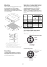
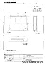
Mounting
This unit does not have power switch. If you
do not connect the IF-2500 to power
switchboard or circuit breaker, install an
external power switch (local supply), locating
it near the IF-2500.
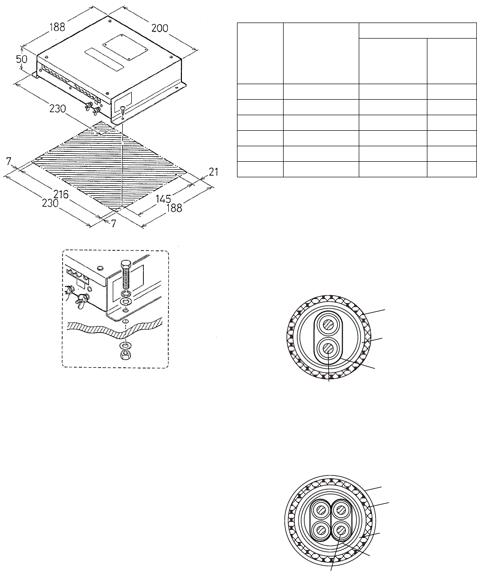
• All dimensions in millimeters.
• For added support, use nuts, bolts and
washers instead of woodscrews.
• Leave sufficient space at the sides and rear
of the unit for maintenance and servicing.
Grounding
To prevent mutual interface, run a ground
wire between the earth terminal on the unit
and ship’s superstructure.
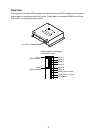
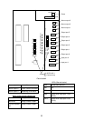
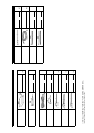
Selection of output data format
The output data format is selectable by
changing a jumper block; A for IEC61162-1
and B for NMEA. For example, to select
NMEA for J4, change the jumper block from A
to B on JP401 and JP402. Do the same on J5
thru J9.
Factory setting
Output Jumper
IEC61162-1
(A)
Current
loop
(B)
J4 JP401/JP402
!
J5 JP501/JP502
!
J6 JP601/JP602
!
J7 JP701/JP702
!
J8 JP801/JP802
!
J9 JP901/JP902
!
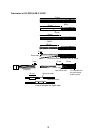
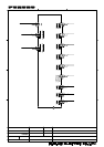
Cable fabrication
Use the following cables (Japan Industrial
Standard cables) or the equivalents.
Conductor
S = 0.75 mm
φ = 1.11 mm
2
TTYCS-1 (Twisted pair cable)
Conductor
S = 0.2 mm
φ = 0.6 mm
2
CO-SPEVV-SB-C 0.2x2P
Armor
Armor
Vinyl sheath
Shield
Shield
Sheath
Sheath
Current loop or IEC 61162-1 signal
Current loop or IEC 61162-1 signal
φ = 10.1 mm
φ = 10.5 mm