


V
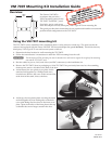
13. Remove and save the three Phillips head screws holding the plastic
molding to the back of the screen.
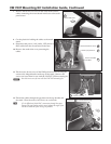
14.
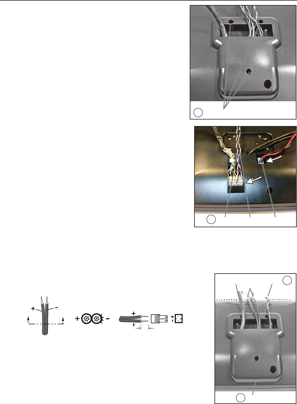
Disconnect the audio, LED, and power cables from the back panel of
the screen.
The audio cables are the black and white pair, wound around a •
ferrite core.
The power cables are the red and black pair, terminated with a •
blue, 2‑pole captive screw connector.
The LED cables are the black and white pair, without a ferrite core.•
N
None of the cables that are connected with a plastic tie should be
disconnected.
N
Save the blue power cable connector for later use.
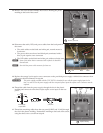
15. Replace the orange 2‑pole captive screw connector on the provided power supply with the blue connector from
the power cable disconnected in step 14.
C
The power supply provided with the TLP 700TV is intended for use with the power supply input in the
base. In order to use the power supply with the rear panel power input the captive screw connector must be
replaced.
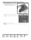
16.
Thread the cable from the power supply through the slot in the plastic
molding and connect it to the direct input captive screw input on the rear
panel.
17. Thread the remaining cables from the rear panel (2 BNC and 1 LAN) through
the slot in the plastic molding. Reattach the molding to the back of the screen,
using the three screws saved from step 13.
Remove (3) Screws
13
PowerLAN S video
Input
17
16
Replace Molding
SECTION A–A
Ridges
Smooth
Power Supply
Output Cord
A A
3/16”
(5 mm) Max.
LED Audio Power
14