


VM 700T Mounting Kit Installation Guide, Continued
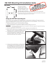
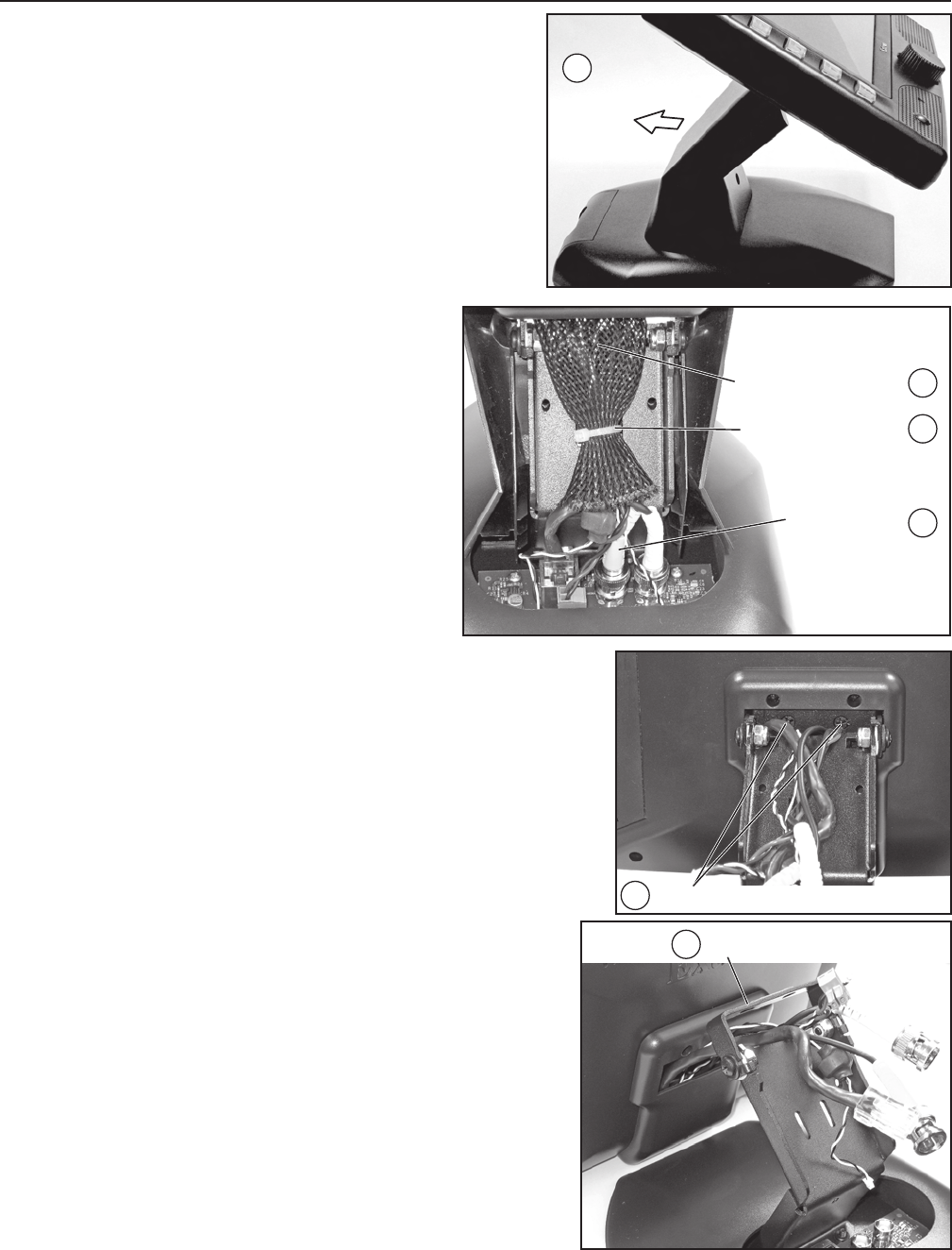
7. Remove the back cover to reveal the metal stand and the
cables connecting the circuit board in the base to the touch
panel screen.
8
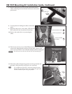
. Cut the plastic tie holding the cables to the metal
stand.
9. Disconnect the power, LAN, audio, LED, and two
BNC cables from the circuit board in the base.
10.
Remove the snake‑skin cover protecting the
cables.
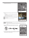
11.
Tilt the screen down to reveal the Phillips head screws securing the
screen to the hinged bracket at the top of the stand. Remove the
screws and save them for use with the VM 700T VESA mounting kit.
N
Save the two screws for use with the VM 700T mounting kit.
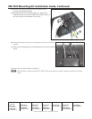
12. Thread the cables through the gap between the top bracket and
the stand. Place the screen, face down, on a soft cloth.
T
If it is difficult to fit the BNC connectors through the space
between the top bracket and the stand, adjust the angle of the
bracket to make the space as large as possible.
Remove back cover.
7
Remove (2) Screws
11
Adjust bracket and thread cables through.
12
Remove Snake-skin Cover
Remove (cut) Plastic Tie
Remove all Cables
from Base
10
8
9