


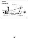
Maintenance
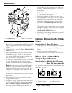
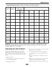
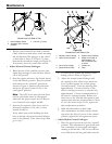
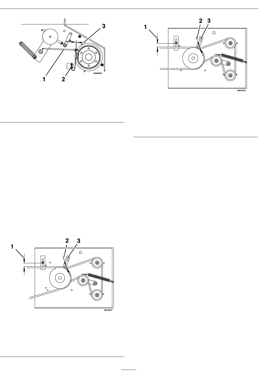
Figure 18
Shown with Blades Disengaged
1. Blade Brake Rod
3. 1/8 inch to 3/16 inch
(.32–.47 cm)
2. Spring Mounting Bolts
4. Check the distance between the spacer and the
nut at the end of the blade brake rod. The
distance should be between 1/8 inch (.32 cm) and
3/16 inch (.47 cm) (see
Figure 18).
5. Engage the PTO and check to make sure the
blade brake pad clears the sheave.
Belt Guide Adjustment
1. Stop engine and wait for all moving parts to stop.
Engage parking brake. Remove key or spark plug
wire(s).
2. Engage the PTO.
3. Check belt guide under the engine deck for proper
adjustment (see Figure 19 and Figure 20). Adjust
as necessary.
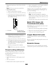
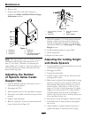
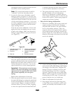
Figure 19
36 inch Belt Guide Location
(Viewed from underneath the engine deck)
1. 1 1/4 inch (3.1 cm) 3. End of slot
2. 1/4 inch (.64 cm)
clearance
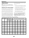
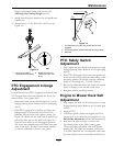
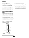
Figure 20
48 inch Belt Guide Location
(Viewed from underneath the engine deck)
1. 1 3/8 inch (3.5 cm) 3. End of slot
2. 1/4 inch (.64 cm)
clearance
Pump Drive Belt Tension
Self-tensioning - No adjustment necessary.
Hydro Drive Linkage
Adjustment
• Adjust Speed Control Linkage and Neutral
Safety Switch:
1. Stop engine and wait for all moving parts to
stop. Engage parking brake. Remove key or
spark plug wire(s).
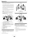
2. Move the speed control lever (located on
the console) to the full forward position and
check the orientation of the tabs on the ends
of the speed control crank (see
Figure 21).
These tabs should be pointing straight down
at the 6 o’clock position or slightly forward.
Adjust the threaded yoke at the bottom of the
speed control linkage (see
Figure 21) until the
tabs are positioned correctly.
33